Fiberopticvideos.com
Welcome
Login / Register

Optical Transceiver Modules


  • COMPUFOX SFP+ Direct Attach Copper Cables Solution

    Overview
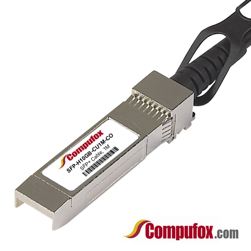
    SFP+ Direct Attach Copper Cable, also known as Twinax Cable, is an SFP+ cable assembly used in rack connections between servers and switches. It consists of a high speed copper cable and two SFP+ copper modules. The SFP+ copper modules allow hardware manufactures to achieve high port density, configurability and utilization at a very low cost and reduced power budget.

    Direct Attach Cable assemblies are a high speed, cost-effective alternative to fiber optic cables in 10Gb Ethernet, 8Gb Fibre Channel and InfiniBand applications. They are suitable for short distances, making them ideal for highly cost-effective networking connectivity within a rack and between adjacent racks. They enable hardware OEMs and data center operators to achieve high port density and configurability at a low cost and reduced power requirement.

    Compufox SFP+ copper cable assemblies meet the industry MSA for signal integrity performance. The cables are hot-removable and hot-insertable: You can remove and replace them without powering off the switch or disrupting switch functions. A cable comprises a low-voltage cable assembly that connects directly into two SFP+ ports, one at each end of the cable. The cables use high-performance integrated duplex serial data links for bidirectional communication and are designed for data rates of up to 10 Gbps.

    Types of SFP+ Direct Attach Copper Cables

    SFP+ Direct Attach Copper Cable assemblies generally have two types which are Passive and Active versions.

    SFP+ Passive Copper Cable
    SFP+ passive copper cable assemblies offer high-speed connectivity between active equipment with SFP+ ports. The passive assemblies are compatible with hubs, switches, routers, servers, and network interface cards (NICs) from leading electronics manufacturers like Cisco, Juniper, etc.
     
    SFP+ Active Copper Cable
    SFP+ active copper cable assemblies contain low power circuitry in the connector to boost the signal and are driven from the port without additional power requirements. The active version provides a low cost alternative to optical transceivers, and are generally used for end of row or middle of row data center architectures for interconnect distances of up to 15 meters.


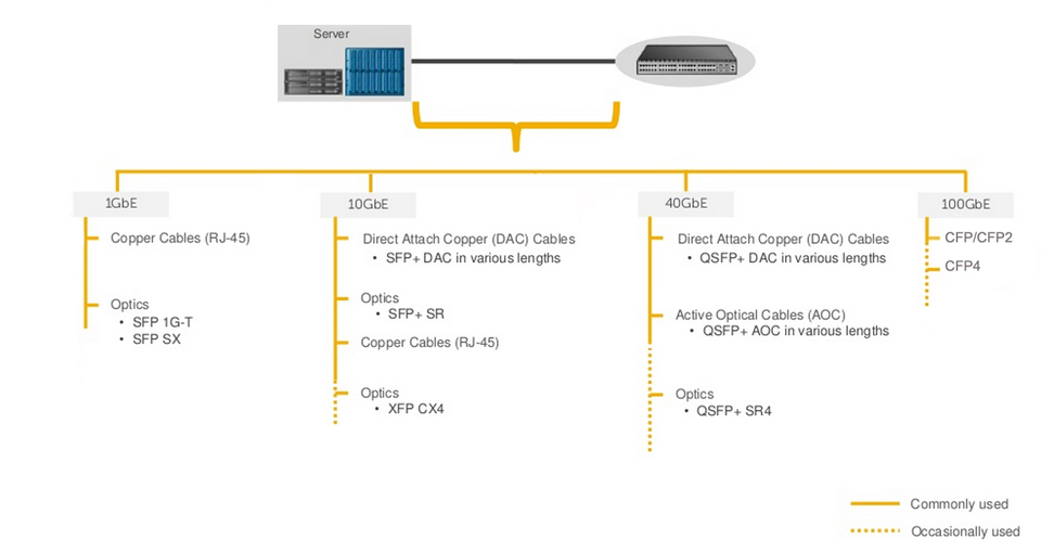
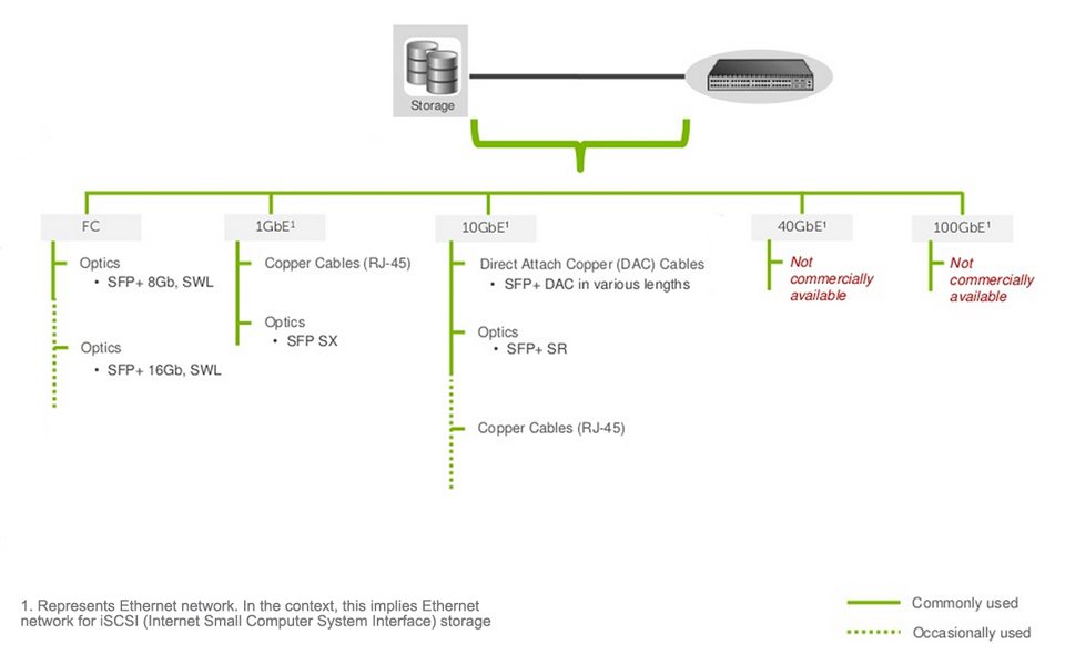
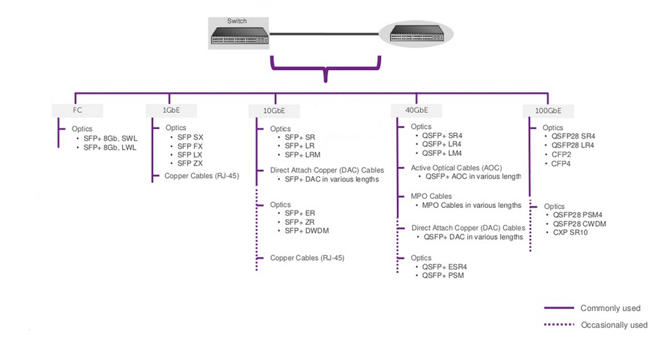
    Applications of SFP+ Direct Attach Copper Cables

    -Networking – servers, routers and hubs
    -Enterprise storage
    -Telecommunication equipment
    -Network Interface Cards (NICs)
    -10Gb Ethernet and Gigabit Ethernet (IEEE802.3ae)
    -Fibre Channel over Ethernet: 1, 2, 4 and 8G
    -InfiniBand standard SDR (2.5Gbps), DDR (5Gbps), and QDR (10Gbps)
    -Serial data transmission
    -High capacity I/O in Storage Area Networks, Network Attached Storage, and Storage Servers
    -Switched fabric I/O such as ultra high bandwidth switches and routers
    -Data center cabling infrastructure
    -High density connections between networking equipment


    Compufox SFP+ Direct Attach Copper Cables Solution

    Compufox SFP+ twinax copper cables are avaliable with custom version and brand compatible version. All of them are 100% compatible with major brands like Cisco, HP, Juniper, Enterasys, Extreme, H3C and so on. If you want to order high quality compatible SFP+ cables and get worldwide delivery, we are your best choice.

    For instance, our compatible Cisco SFP+ Copper Twinax direct-attach cables are suitable for very short distances and offer a cost-effective way to connect within racks and across adjacent racks. We can provide both passive Twinax cables in lengths of 1, 3 and 5 meters, and active Twinax cables in lengths of 7 and 10 meters. (Tips: The lengths can be customized up to the customers' requirements.)

    Features
    -1m/3m/5m/7m/10m/12m available
    -RoHS Compatible
    -Enhanced EMI suppression
    -Low power consumption
    -Compatible to SFP+ MSA
    -Hot-pluggable SFP 20PIN footprint
    -Parallel pair cable
    -24AWG through 30AWG cable available
    -Data rates backward compatible to 1Gbps
    -Support serial multi-gigabit data rates up to 10Gbps
    -Support for 1x, 2x, 4x and 8x Fibre Channel data rates
    -Low cost alternative to fiber optic cable assemblies
    -Pull-to-release retractable pin latch
    -I/O Connector designed for high speed differential signal applications
    -Temperature Range: 0-70°C
    -Passive and Active assemblies available (Active Version: Low Power Consumption: < 0.5W Power Supply: +3.3V)


    FAQ of Compufox SFP+ Direct Attach Copper Cables

    Q: What are the performance requirements for the cable assembly?
    A: Our SFP+ copper passive and active cable assemblies meet the signal integrity requirements defined by the industry MSA SFF-8431. We can custom engineer cable assemblies to meet the requirements of a customer’s specific system architecture.

    Q: Are passive or active cable assemblies required?
    A: Passive cables have no signal amplification in the assembly and rely on host system Electronic Dispersion Compensation (EDC) for signal amplification/equalization. Active cable assemblies have signal amplification and equalization built into the assembly. Active cable assemblies are typically used in host systems that do not employ EDC. This solution can be a cost savings to the customer.

    Q: What wire gauge is required?
    A: We offer SFP+ cable assemblies in wire gauges to support customers' specific cable routing requirements. Smaller wire gauges results in reduced weight, improved airflow and a more flexible cable for ease of routing.

    Q: What cable lengths are required?
    A: Cable length and wire gauge are related to the performance characteristics of the cable assembly. Longer cable lengths require heavier wire gauge, while shorter cable lengths can utilize a smaller gauge cable.

    For all you SFP+ Direct attach cables, please see link below. We carry compatible cables for most major brands.

    http://www.compufox.com/SFP_Cables_s/337.htm


    Read more »
  • How to Install or Remove SFP Transceiver Modules on Cisco Device

    The SFP (small form Factor pluggables) transceiver modules are hot-pluggable I/O devices that plug into module sockets. The transceiver connects the electrical circuitry of the module with the optical or copper network. SFP transceiver modules are the key components in today's transmission network. Thus, it is necessary to master the skill of installing or removing a transceiver modules to avoid unnecessary loss. This tutorial are going to guide you how to install or remove SFP transceiver module in a right way.


    Things you should Know Before Installing or Removing SFP

    Before removing or installing a Transceiver Module you must disconnect all cables, because of leaving these attached will damage the cables, connectors, and the optical interfaces. At the same time please be aware that do not often remove and install an SFP transceiver and it can shorten its useful life. For this reason transceivers should not be removed or inserted more often than is required. Furthermore, transceiver modules are sensitive to static, so always ensure that you use an ESD wrist strap or comparable grounding device during both installation and removal.


    Required Tools

    You will need these tools to install the SFP transceiver module:
    Wrist strap or other personal grounding device to prevent ESD occurrences.Antistatic mat or antistatic foam to set the transceiver on.Fiber-optic end-face cleaning tools and inspection equipment


    Installing SFP Transceiver Modules

    SFP transceiver modules can have three types of latching devices to secure an SFP transceiver in a port socket:
    SFP transceiver with a Mylar tab latch.SFP transceiver with an actuator button latch.SFP transceiver that has a bale-clasp latch.
    Types of SFP Latching

    Determine which type of latch your SFP transceiver uses before following the installation and removal procedures.

    Read more »
  • Optics and Cables Selection for Storage Area Network (SAN)

    Optics and cables are the most important infrastructures of network connectivity. In a storage area network (SAN), switches are used between servers and storage devices. This means that you should make connection with optics and cables between the server and switch, storage and switch as well as the switch and switch. Of course, according to different application environments, you should choose different optics and cables in order to get the best performance. Furthermore, you may need to consider the future expansion of your network. Thus, an economical and effective solution of optics and cables are very necessary.

    Key Factors Influencing Your Decision

    Firstly, there are some key factors which will influence your decision. Thus, you must make sure that what your network really requires. As we mentioned above, an SAN has server, storage device and switches. So, what should we consider in every section of the network?

    1. Server
    Bandwidth: Depending on the application load requirements, customers typically decide whether they want 1GbE, 10GbE, or 40GbE. In some cases, the decision may also be dictated by the type of traffic, e.g. DCB (Data center bridging) requires 10GbE or higher.Cost: Servers claim the highest share of devices deployed in any data center. Choosing a lower cost connectivity option results in a much lower initial deployment cost.Power: In any high density server deployment, a connectivity option which consumes lower power results in much lower OpEx.Distance: Servers are typically connected to a switch over a very short distance, i.e. typically within the same rack or, in some cases, within the same row.Cabling Flexibility: Some customer prefer to make their own copper cables due to variable distance requirement. This requirement limits the choice of connectivity to copper cables only.


    2. Storage
    Reliability: Typical storage traffic is very sensitive to loss. Even a minor loss of traffic may result in major impact on application performance.Qualification: Storage vendor qualification or recommendation plays an important role in this decision due to reasons such as customer support, peace of mind, etc.Latency: Any time spent in transition is time taken away from data processing. Reducing transition time results in much faster application performance. The result may have a direct impact on customers' bottom line, e.g. faster processing of online orders.


    3. Switch
    Bandwidth: On server facing ports, servers typically dictate the per port bandwidth requirement. However, per port bandwidth requirement for the network facing (switch-to-switch) ports denpends on multiple factors including amount of traffic generated by the servers, oversubscription ratios, fiber limitations, ect.Distance: An inter-switch or switch to router connection could range from a few inches to tens of kilometers. Generally, the price of optics increases as the distance increases.Latency: The network topology and application traffic profile (East-west, HPC (High Performance Computing), computer cluster, etc.) and influence the minimun latency that can be tolerated in the network.


    • Server to Switch Connectivity Solution

    • Storage to Switch Connectivity Solution


    • Switch to Switch Connectivity Solution


     COMPUFOX Solutions

    COMPUFOX  offers a comprehensive solution of optics and cables which supports your network from 1GbE to 100GbE. We have a great selection of 1000BASE-T/SX/LX SFP, BiDi SFP, 10GBASE-SR/LR SFP+, DWDM SFP+, whole series 40G QSFP+ optics and cables, as well as the 100G CFP2 and CFP4, etc. which help you solve the cost issue in fiber project. Especially the 40G QSFP+ optics, with the passive optic design, they can be compatible with all the equipment of all major brands. In addition, most of them are ready stock. See Links below:

    Read more »
  • Introduction to Bi-Directional Transceiver Modules

    Almost all modern optical transceivers utilize two fibers to transmit data between switches, firewalls, servers, routers, etc. The first fiber is dedicated to receiving data from networking equipment, and the second fiber is dedicating to transmitting data to the networking equipment. But there is a type of fiber optic transceiver module called BiDi (Bi-Directional) transceiver to break this rule. What's BiDi transceiver? How does it work? And why people believe it will have broad market prospect? This tutorial will give you the answer.

    What's BiDi Transceiver?

    BiDi transceiver is a type of fiber optic transceivers which is used WDM (Wavelength Division Multiplexing) Bi-directional transmission technology so that it can achieve the transmission of optical channels on a fiber propagating simultaneously in both directions. BiDi transceiver is only with one port which uses an integral bidirectional coupler to transmit and receive signals over a single fiber optical cable. Thus, it must be used in pairs.

    How Does BiDi Transceiver Work

    The primary difference between BiDi transceivers and traditional two-fiber fiber optic transceivers is that BiDi transceivers are fitted with Wavelength Division Multiplexing (WDM) couplers, also known as diplexers, which combine and separate data transmitted over a single fiber based on the wavelengths of the light. For this reason, BiDi transceivers are also referred to as WDM transceivers.

    To work effectively, BiDi transceivers must be deployed in matched pairs, with their diplexers tuned to match the expected wavelength of the transmitter and receiver that they will be transmitting data from or to.

    For example, if paired BiDi transceivers are being used to connect Device A (Upstream) and Device B (Downstream), as shown in the figure below, then:

    Transceiver A's diplexer must have a receiving wavelength of 1550nm and a transmit wavelength of 1310nmTransceiver B's diplexer must have a receiving wavelength of 1310nm and a transmit wavelength of 1550nm
    Diplexers at Work in BiDi Optical Ethernet Transceivers

    Advantages of BiDi Transceivers

    The obvious advantage of utilizing BiDi transceivers, such as SFP+- BiDi and SFP-BiDi transceivers, is the reduction in fiber cabling infrastructure costs by reducing the number of fiber patch panel ports, reducing the amount of tray space dedicated to fiber management, and requiring less fiber cable.

    While BiDi transceivers (a.k.a. WDM transceivers) cost more to initially purchase than traditional two-fiber transceivers, they utilize half the amount of fiber per unit of distance. For many networks, the cost savings of utilizing less fiber is enough to more than offset the higher purchase price of BiDi transceivers.

    Read more »
  • 40G QSFP+ Transceiver Modules and DAC/AOC Cables Installation Guide

    To install and remove the transceiver optics in a right way is very necessary to ensure the network to work stably and efficiently. Today, we are going to introduce an installation guide of QSFP transceivers and DAC/AOC cables in 40G network.

    40GbE QSFP+ Transceivers Overview

    40 Gigabit Ethernet (40GbE) aggregation switches are becoming more common in today's data centers. At the heart of the 40GbE network layer is a pair of transceivers connected by a cable. The transceivers are plugged into either network servers or a variety of components including interface cards and switches and connected via the cables such as OM3 and OM4 for multimode application. Additionally DAC (Direct Attach Copper) cables or AOCs (Active Optical Cables) are used for short interconnection as a more cost-effective alternative solution. QSFP+ (Quad Small Form-factor Pluggable Plus) is the most common 40GbE interface type, and also as a high-density 10GbE interface via QSFP+ breakout cables. QSFP+ interfaces a network device (switch, router, media converter or similar device) to a fiber optic or copper cable, supporting data rates from 4x10 Gbps and supports Ethernet, Fibre Channel, InfiniBand and SONET/SDH standards with different data rate options. Compared to CFP (C form-factor pluggable) transceiver modules, QSFP transceiver modules are more compact and more suitable for port-density application. The two basic interface specifications of QSFP+ modules respectively for multimode and single-mode applications are 40GBASE-SR4 and 40GBASE-LR4.

    40GBASE-SR4 QSFP+ Module

    The 40GBASE-SR4 QSFP+ module, conforming to the 802.3ba D3.2 (40GBASE-SR4) standard, provides a 40Gbps optical connection using MPO/MTP® optical connectors. This optical module integrates four data lanes in each direction with 40Gbps aggregate bandwidth and each lane can operate at 10.3125 Gbps. It is used in data centers to interconnect two Ethernet switches with 8 fiber parallel multimode fiber OM3/OM4 cables (transmission distance can be up to 100 meters using OM3 fiber or up to 150 meters using OM4 fiber).


    40GBASE-LR4 QSFP+ Module

    The 40GBBASE-LR4 QSFP+ module, conforming to the 802.3ba (40GBASE-LR4) standard, provides a 40Gbps optical connection using LC optical connectors. This optical module integrates four data lanes in each direction with 40Gbps aggregate bandwidth and each lane can operate at 10.3125 Gbps. It is most commonly deployed between data center or IXP sites with single-mode fiber up to 10 km.

     In addition, to satisfy a number of different objectives including support for MMF and SMF compatibility, there are other types of QSFP+ modules offered by different vendors.

    How to Install/Remove QSFP+ Transceivers and DAC/AOC Cables
     
    Preparations

    To protect a QSFP+ module or cable from ESD (electro-static discharge) damage, before installing or removing a QSFP+ module or cable, be remembered that always wear an ESD wrist strap and make sure that it makes good skin contact and is securely grounded (If you are using ESD gloves, wear the wrist strap outside the ESD glove).

    To Install or Remove a QSFP+ Transceiver Module

    There are two types of clasp designed for a QSFP+ transceiver module—plastic clasp or a metallic clasp. Here uses the metallic clasp type as an example.

    To Install a QSFP+ Transceiver Module

    Step 1. Remove the QSFP+ module from its antistatic container and remove the dust covers from the module optical connector.
    Step 2. Remove any rubber dust covers from the port where you are installing the QSFP+ module.
    Step 3. Pivot the clasp of the module up. (Skip this step if the clasp is plastic.)
    Step 4. Align the module with the port in the chassis, as shown in Figure 1.

    Figure 1. Aligning the module with the port
    Figure 1. Aligning the module with the port

    Step 5. Holding the module, gently push in the module until it is firmly seated in the port.(see Figure 2.)

    Figure 2. Install the QSFP+ module to port
    Figure 2. Install the QSFP+ module to port

    Step 6. Immediately attach the patch cord with MPO connector or duplex LC connector to the QSFP+ transceiver module.(see Figure 3.)

    Figure 3. Install the patch cord to the module
    Figure 3. Install the patch cord to the module

    Note: Install the dust plug for the transceiver module if you are not to install an optical fiber into it.

    To Remove a QSFP+ Transceiver Module

    Step 1. Remove the optical fiber if any.
    Step 2. Pivot the clasp of the module down to the horizontal position. (Skip this step if the clasp is plastic.)
    Step 3. Holding the module, gently pull the module out of the port. (Figure 4)
    Step 4. Place the QSFP+ transceiver into an antistatic bag.

    Figure 4. Remove the QSFP+ module
    Figure 4. Remove the QSFP+ module

    To Install or Remove a 40G QSFP+ Cable

    The installation and removal procedures are the same for QSFP+ DAC cables and QSFP+ AOC cables. Here uses a QSFP+ DAC cable as an example:

    To Install a QSFP+ DAC Cable

    Step 1. Align the QSFP+ transceiver module (with the clasp on top) at one end of the cable with the port in the chassis, as shown in Figure 5.
    Step 2. Horizontally and gently push in the module to fully seat it in the port.

    Figure 5. Installing a QSFP+ DAC cable
    Figure 5. Installing a QSFP+ DAC cable

    To remove a QSFP+ DAC Cable

    Step 1. Gently press and release the QSFP+ transceiver module.(see Figure 6.)
    Step 2. Holding the cable, gently pull the clasp on the cable to pull out the transceiver module.

    Figure 6. Removing a QSFP+ DAC cable
    Figure 6. Removing a QSFP+ DAC cable

    To Install or Remove a 40G QSFP+ to 4x10G SFP+ Cable

    40G QSFP+ to 4x10G SFP+ cable combines one 40G QSFP+ module on one end and four 10G SFP+ module on the other end. The installation and removal procedures of 40G QSFP+ connector are introdueced above. Here only introduced the installation and removal of 10G SFP+ module:

    To Install an SFP+ Transceiver Module

    Step 1. Align the module with the SFP+ port, with the golden plating facing the spring tab (see Figure 7.) in the SFP+ port. If the chassis has two rows of ports, the spring tab in a port is on the bottom in the upper row and on the top in the lower row.
    Step 2. Slightly press the module against the spring tab so you can push the module straight into the port.

    Figure 7. Installing an SFP+ transceiver module
    Figure 7. Installing an SFP+ transceiver module

    To Remove an SFP+ Transceiver Module

    Step 1. Press the module with your thumb, as shown by callout 1 in Figure 8.
    Step 2. Gently pull the clasp on the cable to pull out the transceiver module, as shown by callout 2 in Figure 8.

    Figure 8. Removing an SFP+ transceiver module
    Figure 8. Removing an SFP+ transceiver module

    Verifying the installation

    Execute the display transceiver interface command on the device to verify that the transceiver module or DAC/AOC cable is installed correctly. If the transceiver module and DAC/AOC cable information is displayed correctly, the installation is correct. If an error message is displayed, the installation is incorrect or the transceiver optics is not compatible.

    transceiver interface command

    Conclusion

    As 40 GbE are widely deployed, 40G transceiver optics are ubiquitous. A good practice and correct installation are very important for 40G network system, not only to protect the 40G transceiver optics and device from damage, but also to ensure a stable performance for system. In addition, by executing the display transceiver interface command, we can verify whether the installation is correct. Of course, the premise is that the transceiver optics you use is fully compatible with your device. COMPUFOX offers a comprehensive line of high-compatible 40G transceiver optics, such as 40GBASE-SR4 QSFP+, 40GBASE-LR4 QSFP+ and 40G DACs and AOCs with competitive prices. See Links below:


    Read more »
RSS