Fiberopticvideos.com
Welcome
Login / Register

Most Popular Articles


  • MPO/MTP Solutions for High Density Applications

    As the bandwidth demands grow rapidly, data centers have to achieve ultra-high density in cabling to accommodate all connections. MPO/MTP technology with multi-fiber connectors offers ideal conditions for high-performance data networks in data centers. This article will introduce information about MPO/MTP solutions, such as MPO/MTP trunk cable, MPO/MTP harness cable and MPO/MTP cassettes.

    MTP/MPO Trunk Cable

    MTP/MPO trunk cables are terminated with the MTP/MPO connectors (as shown in the following figure). Trunk cables are available with 12, 24, 48 and 72 fibers. MTP/MPO trunk cables are designed for data center applications. The plug and play solutions uses micro core cable to maximize bend radius and minimize cable weight and size. Besides, MTP/MPO trunk cables also have the following advantages:

    • Saving installation time–With the special plug and play design, MTP/MPO trunk cables can be incorporated and immediately plugged in. It greatly helps reduce the installation time.
    • Decreasing cable volume–MTP/MPO trunk cables have very small diameters, which decrease the cable volume and improve the air-conditioning conditions in data centers.
    • High quality–MTP/MPO trunk cables are factory pre-terminated, tested and packed along with the test reports. These reports serve as long-term documentation and quality control.

    Trunk-Cable

    MPO/MTP Harness Cable

    MPO/MTP harness cable (as shown in the following figure) is also called MPO/MTP breakout cable or MPO/MTP fan-out cable. This cable has a single MTP connector on one end that breaks out into 6 or 12 connectors (LC, SC, ST, etc.). It’s available in 4, 6, 8, or 12 fiber ribbon configurations with lengths about 10, 20, 30 meters and other customized lengths. MPO/MTP harness cable is designed for high density applications with required high performance. It’s good to optimize network performance. Other benefits are shown as below:

    • Saving space–The active equipment and backbone cable is good for saving space.
    • Easy deployment–Factory terminated system saves installation and network reconfiguration time.
    • Reliability–High standard components are used in the manufacturing process to guarantee the product quality.

    Harness-Cable

    MPO/MTP Cassette

    MPO/MTP cassette modules provide secure transition between MPO/MTP and LC or SC discrete connectors. They are used to interconnect MPO/MTP backbones with LC or SC patching. MPO/MTP Cassettes are designed to reduce installation time and cost for an optical network infrastructure in the premises environment. The modular system allows for rapid deployment of high density data center infrastructure

    Cassette

    as well as improved troubleshooting and reconfiguration during moves, addons, and changes. Aside from that, it has other advantages:

    • MPO/MTP interface–MPO/MTP components feature superior optical and mechanical properties.
    • Optimized performance–Low insertion losses and power penalties in tight power budget, high-speed network environments.
    • High density–12 or 24 fiber cassettes can be mounted in 1U scaling up to 72 or in 3U scaling up to 336 discrete LC connectors.

    The above shows that the MPO/MTP system is a good solution for data center requirements. This high density, scalable system is designed to enable thousands of connections.

    Read more »
  • Fiber Optic Patch Panels Tutorial

    What Is Fiber Optic Patch Panel?

    Fiber optic patch panel, or fiber optic patch bay, is a common cable management facilities. It includes a series of connection points of electronic equipment and the mainly connections are fiber optic patch cables. The patch panel allows circuits to be easily arranged and rearranged by simply plugging and unplugging the path cables, or changing the circuit of select signals without the use of expensive dedicated switching equipment. It can be an opened box used to protect the bare fiber and the optical fiber cables, meanwhile it protects spaces for fusion splicing and components connections by fiber adapters. During the unused condition, all fiber optic connectors, fiber patch cables and adapters should be kept away from dust. Fiber optic patch panels help with the installation density of the fiber optic cabling and provide more convenient organization and management.

    A typical fiber optic patch panel has some jacket on the front side to receive short patch cables while on the back of the panel. There are either jacks or punch down blocks that receive the connections of longer and more permanent cables. The patch panels are often used to connect several computers by linking them via the panel, which enables the LAN to connect to the Internet or another WAN.

    Types of Fiber Optic Patch Panels

    According to the installation ways, there are mainly two types of fiber optic patch panels: wall-mounted patch panels and rack-mounted patch panels.

    Wall-Mounted Fiber Optic Patch Panel
    Wall-mounted fiber optic patch panels basically keep 12 different fibers separated from one another. If the amount of the fiber is more than 12, the extra fibers can be moved to a second panel or an engineer can use a panel that is designed to hold more fibers separately. The wall-mounted patch panels can be constructed to hold up to 144 fibers at once.

    Wall-mounted fiber optic patch panels use the inside fiber optic adapters panels, patch cables and pigtails to realize the function of optical fiber distribution. They are used for protective connections for the fiber cables and pigtails in fiber optic cabling and user terminal applications. The patch panels are installed on the indoor wall and terrace to provide a flexible fiber management system for transitional outside plant cable to inside cable and connector assemblies.

    wall mounted fiber optic patch panel


    Rack-Mounted Fiber Optic Patch Panel
    Rack-mounted fiber optic patch panels hold the fibers horizontally and are often designed to open like a drawer. The sliding-opened structure offers engineers an easy access to the optical fibers inside. The rack-mounted patch panels are optional with different kinds of fiber optic adapter ports and pre-installed inner trays and accessories. And fiber optic pigtails of different types are optional, such as SC, FC, ST, LC, E2000 etc. Also, rack-mounted patch panels can be customized by the quantity of optical fibers.

    Rack-mounted fiber patch panels are used to terminated and distributed optical fiber cables. They are convenient to organize and connect the fiber optic links. These patch panels are applied to many fiber optic products, such as DWDM MUX DEMUX, Rack Chassis Splitter, Optical Distribution Frame(ODF) etc. They are fully stable with no risk of movement and offer secure environment for fiber optic adapters, patch cables and pigtails.

    Rack-Mounted Fiber Optic Patch Panel


    According to different applications, fiber optic patch panels can be classified as following:

    Loaded Fiber Optic Patch Panel
    Loaded fiber optic patch panels are usually designed for fitting on a standard 19" rack and can provide the best protection for fiber optic applications. There are rubber grommets on the back of loaded fiber optic patch panels to protect the fiber cables from damage. Each loaded patch panel has fiber splice trays and cable routing spools. What's more, it includes zip ties, cable routing clamps and mounting screws, fiber splice sleeves and installation instructions. There is a special black textured which can be installed a sleek look in the server rack of these loaded fiber patch panels.

    Loaded Fiber Patch Panel


    Swing-Out Fiber Optic Patch Panel
    Swing-out fiber optic patch panels are lightweight and robust patch panels. They are designed for the installation of up to 48 standard optical fibers. These patch panels offer an economic alternative to metal fiber enclosures. The lower tray is designed to gain access to preformed fiber and splice management areas, at the same time, make it easy for installation and dressing of fiber optic cables. All common adapter panel/plate types, includes LC, SC, and ST can be changed with the front plates that can accommodate 6 or 12 duplex, or 12 simplex adapters each.

    Swing-Out Patch Panel


    Fixed Fiber Optic Patch Panel
    Fixed fiber optic patch panels are 19" rack-mountable for connecting up to 24 optical fibers. They are suitable for use with manufactured pigtails or field installation connectors. The installation size is adapted by using appropriate mounting brackets, while the chassis will not be changed. Fixed patch panels are easy to use and more artistic while they can also keep rugged design. These patch panels are easier to terminate, providing greater capacity and easier fiber cable managements. Generally, fixed rack-mounted patch panels do not slide out, but we do offer sliding patch panels for even quicker access to the fiber terminations.

    Fixed Fiber Optic Patch Panel


    Slide-Out Fiber Optic Patch Panel
    Slide out fiber optic patch panels fit with standard 19" or 23" racks and are designed to support both patching and splicing in one unit. Each slide-out patch panel has a slide-out master panel with an integrated tray stop to prevent over extension of fiber cables. The slide-out patch panel also has a two-piece top and swell latch door to allow for easy access to the adapter panels.

    Slide-Out Patch Panel


    High-Density Fiber Optic Patch Panel
    High-density fiber optic patch panels have been engineered to be able to significantly increase density for both patching and splicing. High-density patch panels maximize the amount of adapter panels per rack unit of height, so by utilizing LC quad style adapters you can effectively terminate up to 96 fibers per rack unit of space. There are several other features that make a high density fiber patch panel in an exceptionally nice product to work with. The sliding tray has locking positions to prevent over-extending the fibers. High-density patch panels also have a split top design which allows for easier cable management, and improved strain relief for the cable ingress.

    High Density Fiber Patch Panel


    Fiber Optic Patch and Splice Combos Patch Panel
    Fiber optic patch and splice combos patch panels fit with standard 19" or 23" racks and are designed to support both patching and splicing in one unit. Fiber patch and splice combos have to support termination panels in an upper slide-out shelf with a lower compartment for splice trays in a slide-out shelf. This allows for a full front access application. Blank panels are available to fill unused panel positions.

    Fiber Optic Patch and Splice Combos Patch Panel


    Signature Series Patch Panel
    The Signature Series fiber patch panel offers a solution in which you can adapt the fiber patch panel to many fiber adapter panels or fiber module footprints you want in a way that has never been offered before. This new fiber patch panel series is engineered to allow adaptation to a wide variety of fiber patching applications as well as fiber module installations, including a bulkhead that fits Corning adapter plates. You can now adjust to any of these scenarios with just a simple swap of the fiber bulkhead bracket. The unique master panel design allows for easy and secure routing of fiber without obstructions or compromising your bend radius.

    Signature Series Patch Panel


    LGX Fiber Optic Patch Panel
    LGX fiber optic patch panels are rack-mountable patch panels designed to support the storage of splice trays. They provide high-density fiber connectivity solutions. LGX patch panels have universal mounting hardware to hold fully terminated LGX cassettes. This maximizes the performance of networking space while saving valuable installation time.

    LGX Patch Panel Patch
    Read more »
  • Why Does FTTH Develop So Rapidly?

    FTTH (Fiber to the Home) is a form of fiber optic communication delivery in which the optical fiber reached the end users home or office space from the local exchange (service provider). FTTH was first introduced in 1999 and Japan was the first country to launch a major FTTH program. Now the deployment of  FTTH is increasing rapidly. There are more than 100 million consumers use direct fiber optic connections worldwide. Why does FTTH develop so rapidly?

    FTTH is a reliable and efficient technology which holds many advantages such as high bandwidth, low cost, fast speed and so on. This is why it is so popular with people and develops so rapidly. Now, let’s take a look at its advantages in the following.

    FTTH

    • The most important benefit to FTTH is that it delivers high bandwidth and is a reliable and efficient technology. In a network, bandwidth is the ability to carry information. The more bandwidth, the more information can be carried in a given amount of time. Experts from FTTH Council say that FTTH is the only technology to meet consumers’ high bandwidth demands.
    • Even though FTTH can provide the greatly enhanced bandwidth, the cost is not very high. According to the FTTH Council, cable companies spent $84 billion to pass almost 100 million households a decade ago with lower bandwidth and lower reliability. But it costs much less in today’s dollars to wire these households with FTTH technology.
    • FTTH can provide faster connection speeds and larger carrying capacity than twisted pair conductors. For example, a single copper pair conductor can only carry six phone calls, while a single Fiber pair can carry more than 2.5 million phone calls simultaneously. More and more companies from different business areas are installing it in thousands of locations all over the world.
    • FTTH is also the only technology that can handle the futuristic internet uses when 3D “holographic” high-definition television and games (products already in use in industry, and on the drawing boards at big consumer electronics firms) will be in everyday use in households around the world. Think 20 to 30 Gigabits per second in a decade. No current technologies can reach this purpose.
    • The FTTH broadband connection will bring about the creation of new products as they open new possibilities for data transmission rate. Just as some items that now may seem very common were not even on the drawing board 5 or 10 years ago, such as mobile video, iPods, HDTV, telemedicine, remote pet monitoring and thousands of other products. FTTH broadband connections will inspire new products and services and could open entire new sectors in the business world, experts at the FTTH Council say.
    • FTTH broadband connections will also allow consumers to “bundle” their communications services. For example, a consumer could receive telephone, video, audio, television and just about any other kind of digital data stream using a simple FTTH broadband connection. This arrangement would more cost-effective and simpler than receiving those services via different lines.

    As the demand for broadband capacity continues to grow, it’s likely governments and private developers will do more to bring FTTH broadband connections to more homes. According to a report, Asian countries tend to outpace the rest of the world in FTTH market penetration. Because governments of Asia Pacific countries have made FTTH broadband connections an important strategic consideration in building their infrastructure. South Korea, one of Asian countries, is a world leader with more than 31 percent of its households boasting FTTH broadband connections. Other countries like Japan, the United States, and some western countries are also building their FTTH broadband connections network largely. It’s an inevitable trend that FTTH will continue to grow worldwide.

    Read more »
  • Qualcomm goes big on wifi and IoT with multiple chip launches

    By Tim Skinner        telecoms.com

    Qualcomm has announced new chips and technologies designed to boost domestic wifi coverage, at-home IoT connectivity, wearable tech capability and next generation broadband delivery.

    Starting off with domestic wifi coverage boosting, and Qualcomm launched a new family of 802.11ac platforms designed to optimise device wifi usage by intelligently allocating radio spectrum in the home. It says its new three radio solutions combine two 5 GHz radios and a 2.4 GHz radio to help improve connectivity; and its platform, used on new routers and repeaters, can appropriately dedicate radio in the legacy 2.4 GHz band to devices only compatible with the 802.11n standard. This, in theory, can alleviate congestion on domestic networks and ensure more bandwidth availability for devices compatible with the newer 802.11.ac band.

    Qualcomm says the self-organising features integrated into the new platform means it will become much easier to register and configure new devices on the network; while automatically allocating capacity for devices based on real-time conditions.

    “As people rely on their home network to support more devices accessing the internet and streaming media, Wi-Fi is being stretched to the limit,” said Gopi Sirineni, vice president of product management, Qualcomm Atheros, Inc. “We are changing the game with features designed to deliver the best possible Wi-Fi experiences and now, uniquely, we are driving those technologies into more cost-effective products to extend the benefits to a wider swath of consumers.”

    IoT is also in Qualcomm’s sights, as it unveiled a new chip set targeting low-power smart home devices. It says the QCA4012 chip brings dual band wifi, enhanced security, low power and small form factor for connected devices. Companion SDKs and services from partners Ayla, Exosite and Iota Labs include API interfaces and other tools to support IoT device and cloud integration.

    “IOTA Labs has developed cutting edge IoT solutions integrating Qualcomm Technologies’ latest products with the IOTA Labs platform,” said Amit Singh, director and co-founder, IOTA Labs. “IOTA Labs’s leading edge IoT platform and experience acts as an accelerator for clients to transform their offerings into leading smarter products and services with a lower cost of ownership.”

    The Snapdragon Wear 1100, included in the raft of announcements, joins the product line and targets consumer-led IoT products, including smart-accessories and wearable tech. Qualcomm says it has been designed to target  the wearable segment where a smaller size, longer battery life, smarter sensing, enhanced security. It also comes with a modem capable of LTE, wifi and Bluetooth support.

    “We are delighted to add Snapdragon Wear 1100 to our Snapdragon Wear family, thus making it easier for customers to develop connected wearables with targeted use cases such as kid and elderly tracking,” said Anthony Murray, SVP of IoT for Qualcomm Technologies. “We are actively working with the broader ecosystem to accelerate wearables innovation and are excited to announce a series of customer collaborations today.”

    Finally, Qualcomm also announced a fixed networking launch which it claims will help operators deliver up to 1 Gbps data rates on existing infrastructure up to 100 meters. The GigaDSL chipsets are intended to support gigabit data rates on existing telephone lines providing a high-speed extension for VDSL without losing spectrum capacity. It says existing infrastructure can be upgraded to the new processors without having to rip up the network and start again. The product line will become available from June for both fibre to the building and customer premises equipment.

    “With these new GigaDSL product offerings, we are able to meet carriers’ broadband goals, complementing fiber deployment in time for major events, such as the 2018 Winter Games in Korea and the 2020 Summer Games in Japan,” said Irvind Ghai, VP of product management at Qualcomm Atheros.


    Read more »
  • Mode Conditioning Patch Cable Tutorial

    There are bandwidth limitations of multimode fiber. Most current LAN networks are composed of about 90% multimode fiber. As the fiber cable plant is upgraded to single mode fiber cables, we must also provide a migration path that continues to reuse the installed multimode cable plant for as long as possible. However, there are some technical issues involved when using single mode equipment on existing multimode cable plant. The biggest problem is caused by Differential Mode Delay (DMD). It refers when a fast rise-time laser pulse is applied to multimode fiber, significant pulse broadening occurs due to the difference in propagation times of different modes within the fiber.

    To solve the problem, mode conditioning patch cable was developed as a solution for network applications where Gigabit Ethernet hubs with laser based transmitters are deployed. Mode conditioning patch cable is the mean to achieve the drive distance of installed fiber plant beyond its original intended applications. It allows customer upgrading their hardware technology without the cost of upgrading fiber plant. In addition, mode conditioning patch cable significantly improves data signal quality while increasing the transmission distance.


    What is Mode Conditioning Patch Cable?

    MCP


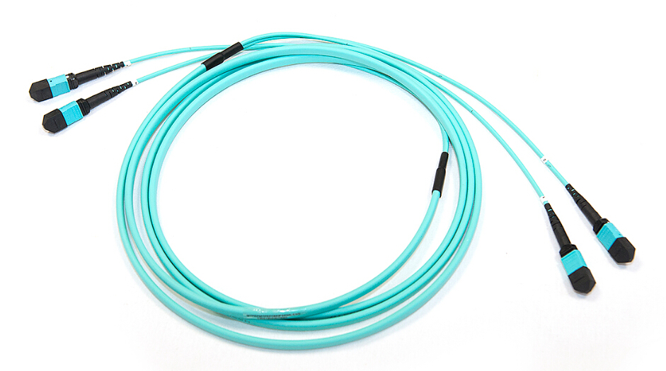
    Mode Conditioning Patch Cable, or Mode Conditioning Patchcord (MCP), is a duplex multimode patch cable that has a small length of single mode fiber at the start of the transmission length. Designed to "condition" the laser launch and obtain an effective bandwidth closer to that measured by the overfilled launch method, the MCP allows for laser transmitters to operate at gigabit rates over multimode fiber without being limited by DMD. The point is to excite a large number of modes in the fiber, weighted in the mode groups that are highly excited by overfill launch conditions, and to avoid exciting widely separated mode groups with similar power levels. This is achieved by launching the laser light into a single mode fiber, then coupling it into a multimode fiber that is off-center relative to the single mode fiber core. This is shown beside.

    Tips: Different offsets are required for 50µm and 62.5µm multimode fibers. Engineers have found that an offset of 17~23 µm can achieve an effective modal bandwidth equivalent to the overfill launch method for 62.5µm multimode fibers. And an offset of 10~16 µm is good for 50µm multimode fibers.

    The basic principle behind the cable is to launch laser into the small section of single mode fiber. The other end of single mode fiber is coupled to the multimode section of the cable with the offset from the center of the multimode fiber. This patch cable is required with transceivers (e.g.1000BASE-LX/LH, 10GBASE-LX4 and 10GBASE-LRM) that use both single mode and multimode fibers. When launching into multimode fiber, the transceiver can generate multiple signals that causes DMD which can severly limit transmission distances. The MCP removes these multiple signals, eliminating problems at the receiver end. Here is a figure that shows an MCP and how it is typically connected to a transceiver module. When required, it is inserted between a transceiver module and the multimode cable plant.

    MCP using with Transceivers


    Requirements for Using MCPs in Laser-Based Transmissions

    Gigabit Ethernet

    The requirement for MCP is specified only for 1000BASE-LX/LH transceivers transmitting in the 1300nm window and in applications over multimode fiber. MCP should never be used in 1000BASE-SX links in the 850nm window. MCP is required for 1000BASE-LX/LH applications over FDDI-grade, OM1, and OM2 fiber types. MCP should never be used for applications over OM3, also known as "laser-optimized fiber".

    Note:
     
    1. In some cases, customers might experience that a link would be operating properly over FDDI-grade, OM1 or OM2 fiber types without MCP. However please note there is no guarantee link will be operating properly over time, and the recommendation remains to use the MCP.
     
    2. There is a risk associated to this type of nonstandard deployment without MCP, especially when the jumper cable is an FDDI-grade or OM1 type. In such case the power coupled directly into a 62.5µm fiber could be as high as a few dBm and the adjacent receiver will be saturated. This can cause high bit error rate, link flaps, link down status and eventually irreversible damaged to the device.
     
    3. In the event customers remain reluctant to deploy MCP cables, and for customers using OM3 cables, please measure the power level before plugging the fiber into the adjacent receiver. When the received power is measured above -3dBm, a 5dB attenuator for 1300nm should be used and plugged at the transmitter source of the optical module on each side of the link.
     
    4. Another alternative for short reaches within the same location is to use a single-mode patch cable. There will be no saturation over single-mode fiber.


    10-Gigabit Ethernet

    The requirement for MCP is specified only for 10GBASE-LX4 and 10GBASE-LRM transceivers transmitting in the 1300nm window and in applications over multimode fiber. MCP should never be used in 10GBASE-SR links in the 850nm window. MCP is required for 10GBASE-LX4 and 10GBASE-LRM applications over FDDI-grade, OM1, and OM2 fiber types. MCP should never be used for applications over OM3, also known as "laser-optimized fiber."

    Notes for 10GBASE-LX4:
     
    1. In some cases, customers might experience that a link would be operating properly over OM2 fiber type without MCP. However chances of experiencing a properly operating link over FDDI-grade or OM1 fiber types without MCP are very low.
     
    2. In the event customers remain reluctant to deploy MCP cables over OM2, and for customers using OM3 cables, it is required to a plug a 5dB attenuator for 1300nm at the transmitter source of the optical module on each side of the link in order to avoid saturation, and potential subsequent link flaps and damage to the device.
     
    3. Another alternative for short reaches within the same location is to use a single-mode patch cable. There will be no saturation over single-mode fiber. Please note the 10GBASE-LX4 devices can reach up to 10 km over single-mode fiber as per compliance to IEEE.
     
    Notes for 10GBASE-LRM:
     
    1. For customers using OM3 fiber type, MCP should not be used. It is highly recommended to measure the power level before plugging the fiber into the adjacent receiver. When the received power is measured to be above 0.5dBm, a 5dB attenuator for 1300nm should be used and plugged at the transmitter source of the optical module on each side of the link.
     
    2. Another alternative for short reaches within the same location is to use a single-mode patch cable. There will be no saturation over single-mode fiber. Please note the 10GBASE-LRM devices can reach up to 300 meters over single-mode fiber.


    Notes for the Installation of MCPs

    When using 1000BASE-LX/LH, 10GBASE-LX4 and 10GBASE-LRM transceivers with legacy 62.5µm or 50µm multimode fiber, you must install MCP between the transceiver and the multimode fiber cable on both ends of the link. The MCP is required for all links over FDDI-grade, OM1 and OM2 fiber types, and should never be used for applications over OM3 and more recent fiber types.

    Note: It is not recommended using 1000BASE-LX/LH, 10GBASE-LX4 and 10GBASE-LRM transceivers with multimode fiber and no patch cable for very short link distances (tens of meters). The result could be an elevated Bit Error Rate (BER) and receiver damage.

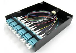
    The MCP is installed between the transceiver and the patch panel. Two MCPs are required per installation. To install the patch cable, follow these steps:
     
    Step 1 - Plug the single mode fiber connector into the transmit bore of the transceiver.
    Step 2 - Plug the other half of the duplex connector into the receive bore of the transceiver.
    Step 3 - At the other end of the patch cable, plug both multimode connectors into the patch panel.
    Step 4 - Repeat Step 1 through Step 3 for the second transceiver located at the other end of the network link.
    Read more »
RSS