Fiberopticvideos.com
Welcome
Login / Register

Most Popular Articles


  • Fiber Media Converter Tutorial

    Fiber media converter is a cost-effective solution to overcome the bandwidth and distance limitations of traditional network cable. It dramatically increases the bandwidth and transmission distance of the local area network (LAN) by allowing the use of fiber and integrating new equipment into existing cabling infrastructure. To better understand it, this article will give an overview of fiber media converter.

    What is Fiber Media Converter?

    Fiber media converter is a transfer media that connects two dissimilar media types. Generally, it is a device that converts electrical signal used in copper unshielded twisted paired (UTP) network cabling into light waves used in fiber optic cabling, and vice versa. This kind of fiber media converter is called copper-to-fiber media converter that provides a simple way to introduce fiber into a LAN without tearing out the existing copper wiring or making changes to copper-based switches. Furthermore, there is another kind of fiber media converter that supports fiber-to-fiber conversion, which provides connections between dual-fiber and single-fiber or between multimode fiber and single-mode fiber. Fiber-to-fiber media converters also provide a cost-effective solution for wavelength conversion in Wavelength Division Multiplexing (WDM) applications, which are also known as transponders.

    Types of Fiber Media Converters

    There are a wide variety of fiber media converters available in the market. According to different criteria, fiber media converters may be classified into different types.

    Managed VS Unmanaged

    The managed fiber media converter has the functions of networking monitoring, fault detection and remote management. It helps the network administrator to easily monitor and manage the network. An unmanaged fiber media converter, however, allows for simple communication with other devices and does not have the monitoring and management functions that managed fiber media converter has.

    Platform: Stand-Alone VS Modular Chassis-Based

    According to the platform type, fiber media converters can be divided into stand-alone fiber media converter and modular chassis-based fiber media converter. Stand-alone fiber media converters are designed to be used in where a single or limited number of converter(s) need(s) to be quickly implemented. Modular chassis-based fiber media converters, however, are used in high-density applications that multiple points of copper and/or fiber integration are essential.

    Copper-to-Fiber Media Converter VS Fiber-to-Fiber Media Converter

    According to media types, fiber media converters may be classified into copper-to-fiber media converter and fiber-to-fiber media converter.

    Copper-to-Fiber Media Converter

    Copper-to-fiber media converters are the key to integrating fiber into a copper infrastructure. According to different applications, copper-to-fiber media converters may be further divided into Ethernet copper-to-fiber media converters, video-to-fiber media converters and serial-to-fiber media converters.

    Fs copper-to-fiber-media-converter.jpg

    Ethernet Copper-to-Fiber Media Converter

    This kind of fiber media converter supports the IEEE 802.3 standard and provides connectivity for Ethernet, fast Ethernet, Gigabit and 10 Gigabit Ethernet devices. SC to RJ45 media converters, SFP to RJ45 media converters, PoE media converters, mini media converters and industrial media converters are all among this type.

    Fs ethernet-copper-to-fiber-media-converter.jpg

    The SC to RJ45 media converter comes with RJ45 and SC ports, which is designed to be used with fiber cable preterminated with the SC-type connector.The SFP to RJ45 media converter comes with RJ45 and pluggable fiber optics ports, which allows for flexible network configurations using SFP transceivers. PoE media converters can transparently connect copper to fiber while providing Power-over-Ethernet (PoE) to standards-based PoE compliant devices such as IP cameras, VoIP phones and wireless access points. Mini media converter is a miniature-sized copper-to-fiber converter. It is ideal for bringing fiber to the desktop and for mobile applications where light weight, compact size and low power are required.Industrial media converters are compact and robust devices designed to convert Gigabit Ethernet or Fast Ethernet networks into Gigabit or Ethernet fiber optic networks.


    Video Copper-to-Fiber Media Converter

    Video copper-to-fiber media converter also called fiber optic multiplexer, which is used to transmit and receive signals such as video, audio, data and Ethernet. fiber optic multiplexers are devices that process two or more light signals through a single optical fiber (as shown in the following figure), increasing the amount of information that can be carried through a network. Since signals may be analog or digital, video copper-to-fiber can be further divided into converters transmitting analog signals and converters transmitting digital signals. As the name applies, converters transmitting analog signals give amplitude or frequency modulation of the electric signal and then convert it into optical signal. Demodulation will also be done at the receiving end. Converters transmitting digital signals, however, digitize and multiplex the video, audio and data signals, transforming multiple low-speed digital signals into one high-speed signal. This high speed signal will then be turned into optical signal transmitting on a fiber.

    Fs vedio-copper-to-fiber-media-converter.png

    In accordance with different applications, there are three commonly used video copper-to-fiber media converters: plesiochronous digital hierarchy (PDH) multiplexers, synchronous digital hierarchy (SDH) multiplexers and synchronous plesiochronous sigital hierarchy (SPDH) multiplexers. Using the PDH fiber transmission technologies, PDH multiplexers are E1 point-to-point optical transport equipment. And the general transmission capacity of this kind of multiplexer is 4E1,8E1 and 16E1. SDH multiplexers, having a large transmission capacity, are designed to support end-to-end provisioning and management of services across all segments of the optical network. SPDH multiplexers adopt both PDH and SDH technologies. It is a PDH transmission system that based on the PDH code speed adjustment principle at the same time, use as far as possible parts of the SDH network technology.

    Serial-to-Fiber Media Converter

    This kind of media converter provides fiber extension for serial protocol copper connections. It accepts serial data on one port in RS232, RS485 or other format and convert the serial data stream into a fiber optic signal to a matching unit at the other end of the fiber span.

    Fs serial-to-fiber-media-converter.jpg

    Fiber-to-Fiber Media Converter

    Fiber-to-fiber media converters are used to extend network distance by providing connectivity between multimode and single-mode fiber, between different “power” fiber sources and between dual fiber and single-fiber. Furthermore, they also support conversion from one wavelength to another. Mode converter and WDM OEO transponder are two common types of fiber-to-fiber media converters.

    Mode Converter

    A mode converter can be used to allow for an adiabatic transition between two optical modes. Other than cross-connecting different fiber types, mode converters can also re-generate optical signals, extending transmission distance and double fiber cable usage. It is usually applied in multi-mode to single-mode fiber conversion.

    Fs mode-converter.jpg

    WDM OEO Transponder

    When a fiber media converter is used in the WDM system, it is called WDM OEO transponder which converts the incoming signal from the end or client device to a WDM wavelength. WDM OEO transponders are often used for dual fiber to single fiber conversion and wavelength conversion.

    Networks may require conversion between dual and single-fiber, depending in the type of equipment and the fiber installed in the facility. The following figures shows the role of WDM transponder played in the fiber optic network.

    Fs wdm-oeo-transponder-dual-fiber-to-single-fiber-conversion.jpg

    WDM OEO transponders are capable of wavelength conversion by using small form-factor pluggable (SFP) transceivers that transmit different wavelengths, provide a cost-effective solution to convert from standard optical wavelengths (850nm, 1310nm and 1550nm) of legacy equipment to optical wavelengths specified for WDM networks.

    Fs wdm-oeo-transponder-wavelength-conversion.jpg

    Selection Guide of Fiber Media Converters

    A proper fiber media converter may provide a cost-effective solution for extending Ethernet transmission while reducing cable and labor cost. When selecting fiber media converters for your network, the following points should be taken into consideration:

    The chip of the fiber media converter shall work in both full-duplex and half-duplex systems. The reason is that some N-Way Switches and HUBs may use half-duplex mode operations, and serious collision and data loss may be caused if the fiber media converter only supports full-duplex operation. Connection test should be done between the fiber media converter and different optical fiber splices. Otherwise, data loss and unstable transmission may happen on account of incompatibility between different fiber media converters.To ensure the proper operation of the fiber media converter, temperature measurement is also necessary. This is because the fiber media converter may not work correctly in high-temperature environment. Thus, it is important to know exactly its working temperature.Safety device guarding against data loss shall be equipped in the fiber media converter.The fiber media converter shall meet the IEEE802.3 standards. If not, there must be a risk of incompatibility.
     
    For a selection of Compufox fiber media converters, please click on the link below:
     
     
    Read more »
  • Cisco StackWise and StackWise Plus Technology

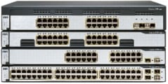
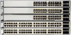
    This white paper provides an overview of the Cisco StackWise and Cisco StackWise Plus technologies and the specific mechanisms that they use to create a unified, logical switching architecture through the linkage of multiple, fixed configuration switches. This paper focuses on the following critical aspects of the Cisco StackWise and Cisco StackWise Plus technologies: stack interconnect behavior, stack creation and modification; Layer 2 and Layer 3 forwarding; and quality-of-service (QoS) mechanisms. The goal of the paper is to help the reader understand how the Cisco StackWise and StackWise Plus technologies deliver advanced performance for voice, video, and Gigabit Ethernet applications. First, this white paper will discuss the Cisco Catalyst 3750 Series Switches and StackWise and second, the Cisco Catalyst 3750-E and Catalyst 3750-X Series Switches with StackWise Plus will be discussed, highlighting the differences between the two. Please note that the Cisco Catalyst 3750-E and Catalyst 3750-X will run StackWise Plus when connected to a stack of all Cisco Catalyst 3750-E and Catalyst 3750-X switches, while it will run StackWise if there is one or more Cisco Catalyst 3750 in the stack. (See Figures 1 and 2.)

    Figure 1. Stack of Cisco Catalyst 3750 Series Switches with StackWise Technology

    Figure 2. Stack of Cisco Catalyst 3750-E Series Switches with StackWise and StackWise Plus Technologies

    Technology Overview

    Cisco StackWise technology provides an innovative new method for collectively utilizing the capabilities of a stack of switches. Individual switches intelligently join to create a single switching unit with a 32-Gbps switching stack interconnect. Configuration and routing information is shared by every switch in the stack, creating a single switching unit. Switches can be added to and deleted from a working stack without affecting performance.

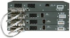
    The switches are united into a single logical unit using special stack interconnect cables that create a bidirectional closed-loop path. This bidirectional path acts as a switch fabric for all the connected switches. Network topology and routing information is updated continuously through the stack interconnect. All stack members have full access to the stack interconnect bandwidth. The stack is managed as a single unit by a master switch, which is elected from one of the stack member switches.

    Each switch in the stack has the capability to behave as a master or subordinate (member) in the hierarchy. The master switch is elected and serves as the control center for the stack. Both the master member switches act as forwarding processors. Each switch is assigned a number. Up to nine separate switches can be joined together. The stack can have switches added and removed without affecting stack performance.

    Each stack of Cisco Catalyst 3750 Series Switches has a single IP address and is managed as a single object. This single IP management applies to activities such as fault detection, virtual LAN (VLAN) creation and modification, security, and QoS controls. Each stack has only one configuration file, which is distributed to each member in the stack. This allows each switch in the stack to share the same network topology, MAC address, and routing information. In addition, it allows for any member to become the master, if the master ever fails.

    The Stack Interconnect Functionality

    Cisco StackWise technology unites up to nine individual Cisco Catalyst 3750 switches into a single logical unit, using special stack interconnect cables and stacking software. The stack behaves as a single switching unit that is managed by a master switch elected from one of the member switches. The master switch automatically creates and updates all the switching and optional routing tables. A working stack can accept new members or delete old ones without service interruption.

    Bidirectional Flow

    To efficiently load balance the traffic, packets are allocated between two logical counter-rotating paths. Each counter-rotating path supports 16 Gbps in both directions, yielding a traffic total of 32 Gbps bidirectionally. The egress queues calculate path usage to help ensure that the traffic load is equally partitioned.

    Whenever a frame is ready for transmission onto the path, a calculation is made to see which path has the most available bandwidth. The entire frame is then copied onto this half of the path. Traffic is serviced depending upon its class of service (CoS) or differentiated services code point (DSCP) designation. Low-latency traffic is given priority.

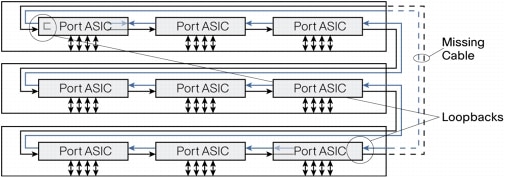
    When a break is detected in a cable, the traffic is immediately wrapped back across the single remaining 16-Gbps path to continue forwarding.

    Online Stack Adds and Removals

    Switches can be added and deleted to a working stack without affecting stack performance. When a new switch is added, the master switch automatically configures the unit with the currently running Cisco IOS ® Software image and configuration of the stack. The stack will gather information such as switching table information and update the MAC tables as new addresses are learned. The network manager does not have to do anything to bring up the switch before it is ready to operate. Similarly, switches can be removed from a working stack without any operational effect on the remaining switches. When the stack discovers that a series of ports is no longer present, it will update this information without affecting forwarding or routing.

    Physical Sequential Linkage

    The switches are physically connected sequentially, as shown in Figure 3. A break in any one of the cables will result in the stack bandwidth being reduced to half of its full capacity. Subsecond timing mechanisms detect traffic problems and immediately institute failover. This mechanism restores dual path flow when the timing mechanisms detect renewed activity on the cable.

    Figure 3. Cisco StackWise Technology Resilient Cabling

    Subsecond Failover

    Within microseconds of a breakage of one part of the path, all data is switched to the active half of the bidirectional path (Figure 4).

    Figure 4. Loopback After Cable Break

    The switches continually monitor the stack ports for activity and correct data transmission. If error conditions cross a certain threshold, or there is insufficient electromagnetic contact of the cable with its port, the switch detecting this then sends a message to its nearest neighbor opposite from the breakage. Both switches then divert all their traffic onto the working path.

    Single Management IP Address

    The stack receives a single IP address as a part of the initial configuration. After the stack IP address is created, the physical switches linked to it become part of the master switch group. When connected to a group, each switch will use the stack IP address. When a new master is elected, it uses this IP address to continue interacting with the network.

    Stack Creation and Modification

    Stacks are created when individual switches are joined together with stacking cables. When the stack ports detect electromechanical activity, each port starts to transmit information about its switch. When the complete set of switches is known, the stack elects one of the members to be the master switch, which will be responsible for maintaining and updating configuration files, routing information, and other stack information. The entire stack will have a single IP address that will be used by all the switches.

    1:N Master Redundancy

    1:N master redundancy allows each stack member to serve as a master, providing the highest reliability for forwarding. Each switch in the stack can serve as a master, creating a 1:N availability scheme for network control. In the unlikely event of a single unit failure, all other units continue to forward traffic and maintain operation.

    Master Switch Election

    The stack behaves as a single switching unit that is managed by a master switch elected from one of the member switches. The master switch automatically creates and updates all the switching and optional routing tables. Any member of the stack can become the master switch. Upon installation, or reboot of the entire stack, an election process occurs among the switches in the stack. There is a hierarchy of selection criteria for the election.

    1. User priority - The network manager can select a switch to be master.

    2. Hardware and software priority - This will default to the unit with the most extensive feature set. The Cisco Catalyst 3750 IP Services (IPS) image has the highest priority, followed by Cisco Catalyst 3750 switches with IP Base Software Image (IPB).

    Catalyst 3750-E and Catalyst 3750-X run the Universal Image. The feature set on the universal image is determined by the purchased license. The "show version" command will list operating license level for each switch member in the stack.

    3. Default configuration - If a switch has preexisting configuration information, it will take precedence over switches that have not been configured.

    4. Uptime - The switch that has been running the longest is selected.

    5. MAC address - Each switch reports its MAC address to all its neighbors for comparison. The switch with the lowest MAC address is selected.

    Master Switch Activities

    The master switch acts as the primary point of contact for IP functions such as Telnet sessions, pings, command-line interface (CLI), and routing information exchange. The master is responsible for downloading forwarding tables to each of the subordinate switches. Multicast and unicast routing tasks are implemented from the master. QoS and access control list (ACL) configuration information is distributed from the master to the subordinates. When a new subordinate switch is added, or an existing switch removed, the master will issue a notification of this event and all the subordinate switches will update their tables accordingly.

    Shared Network Topology Information

    The master switch is responsible for collecting and maintaining correct routing and configuration information. It keeps this information current by periodically sending copies or updates to all the subordinate switches in the stack. When a new master is elected, it reapplies the running configuration from the previous master to help ensure user and network continuity. Note that the master performs routing control and processing. Each individual switch in the stack will perform forwarding based on the information distributed by the master.

    Subordinate Switch Activities

    Each switch has tables for storing its own local MAC addresses as well as tables for the other MAC addresses in the stack. The master switch keeps tables of all the MAC addresses reported to the stack. The master also creates a map of all the MAC addresses in the entire stack and distributes it to all the subordinates. Each switch becomes aware of every port in the stack. This eliminates repetitive learning processes and creates a much faster and more efficient switching infrastructure for the system.

    Subordinate switches keep their own spanning trees for each VLAN that they support. The StackWise ring ports will never be put into a Spanning Tree Protocol blocking state. The master switch keeps a copy of all spanning tree tables for each VLAN in the stack. When a new VLAN is added or removed, all the existing switches will receive a notification of this event and update their tables accordingly.

    Subordinate switches wait to receive copies of the running configurations from the master and begin to start transmitting data upon receipt of the most current information. This helps ensure that all the switches will use only the most current information and that there is only one network topology used for forwarding decisions.

    Multiple Mechanisms for High Availability

    The Cisco StackWise technology supports a variety of mechanisms for creating high resiliency in a stack.

    CrossStack EtherChannel® technology - Multiple switches in a stack can create an EtherChannel connection. Loss of an individual switch will not affect connectivity for the other switches.

    Equal cost routes - Switches can support dual homing to different routers for redundancy.

    1:N master redundancy - Every switch in the stack can act as the master. If the current master fails, another master is elected from the stack.

    Stacking cable resiliency - When a break in the bidirectional loop occurs, the switches automatically begin sending information over the half of the loop that is still intact. If the entire 32 Gbps of bandwidth is being used, QoS mechanisms will control traffic flow to keep jitter and latency-sensitive traffic flowing while throttling lower priority traffic.

    Online insertion and removal - Switches can be added and deleted without affecting performance of the stack.

    Distributed Layer 2 forwarding - In the event of a master switch failure, individual switches will continue to forward information based on the tables they last received from the master.

    RPR+ for Layer 3 resiliency - Each switch is initialized for routing capability and is ready to be elected as master if the current master fails. Subordinate switches are not reset so that Layer 2 forwarding can continue uninterrupted. Layer 3 Nonstop Forwarding (NSF) is also supported when two or more nodes are present in a stack.

    Layer 2 and Layer 3 Forwarding

    Cisco StackWise technology offers an innovative method for the management of Layer 2 and Layer 3 forwarding. Layer 2 forwarding is done with a distributed method. Layer 3 is done in a centralized manner. This delivers the greatest possible resiliency and efficiency for routing and switching activities across the stack.

    Forwarding Resiliency During Master Change

    When one master switch becomes inactive and while a new master is elected, the stack continues to function. Layer 2 connectivity continues unaffected. The new master uses its hot standby unicast table to continue processing unicast traffic. Multicast tables and routing tables are flushed and reloaded to avoid loops. Layer 3 resiliency is protected with NSF, which gracefully and rapidly transitions Layer 3 forwarding from the old to new master node.

    High-Availability Architecture for Routing Resiliency Using Routing Processor Redundancy+

    The mechanism used for high availability in routing during the change in masters is called Routing Processor Redundancy+ (RPR+). It is used in the Cisco 12000 and 7500 Series Routers and the Cisco Catalyst 6500 Series Switch products for high availability. Each subordinate switch with routing capability is initialized and ready to take over routing functions if the master fails. Each subordinate switch is fully initialized and connected to the master. The subordinates have identical interface addresses, encapsulation types, and interface protocols and services. The subordinate switches continually receive and integrate synchronized configuration information sent by the current master and monitor their readiness to operate through the continuous execution of self-tests. Reestablishment of routes and links happens more quickly than in normal Layer 3 devices because of the lack of time needed to initialize the routing interfaces. RPR+ coupled with NSF provides the highest performance failover forwarding.

    Adding New Members

    When the switching stack has established a master, any new switch added afterward automatically becomes a subordinate. All the current routing and addressing information is downloaded into the subordinate so that it can immediately begin transmitting traffic. Its ports become identified with the IP address of the master switch. Global information, such as QoS configuration settings, is downloaded into the new subordinate member.

    Cisco IOS Software Images Must Be Identical

    The Cisco StackWise technology requires that all units in the stack run the same release of Cisco IOS Software. When the stack is first built, it is recommended that all of the stack members have the same software feature set - either all IP Base or all IP Services. This is because later upgrades of Cisco IOS Software mandate that all the switches to be upgraded to the same version as the master.

    Automatic Cisco IOS Software Upgrade/Downgrade from the Master Switch

    When a new switch is added to an existing stack, the master switch communicates with the switch to determine if the Cisco IOS Software image is the same as the one on the stack. If it is the same, the master switch sends the stack configuration to the device and the ports are brought online. If the Cisco IOS Software image is not the same, one of three things will occur:

    1. If the hardware of the new switch is supported by the Cisco IOS Software image running on the stack, the master will by default download the Cisco IOS Software image in the master's Flash memory to the new switch, send down the stack configuration, and bring the switch online.

    2. If the hardware of the new switch is supported by the Cisco IOS Software image running on the stack and the user has configured a Trivial File Transfer Protocol (TFTP) server for Cisco IOS Software image downloads, then the master will automatically download the Cisco IOS Software image from the TFTP server to the new switch, configure it, then bring it online.

    3. If the hardware of the new switch is not supported by the Cisco IOS Software image running on the stack, the master will put the new switch into a suspended state, notify the user of a version incompatibility, and wait until the user upgrades the master to a Cisco IOS Software image that supports both types of hardware. The master will then upgrade the rest of the stack to this version, including the new switch, and bring the stack online.

    Upgrades Apply to All Devices in the Stack

    Because the switch stack behaves like a single unit, upgrades apply universally to all members of the stack at once. This means that if an original stack contains a combination of IP Base and IP services software feature sets on the various switches, the first time a Cisco IOS Software upgrade is applied, all units in the stack will take on the characteristic of the image applied. While this makes it much more efficient to add functionality to the stack, it is important to make sure all applicable upgrade licenses have been purchased before allowing units to be upgraded from IP Base .to IP Services functions. Otherwise, those units will be in violation of Cisco IOS Software policy.

    Smart Unicast and Multicast - One Packet, Many Destinations

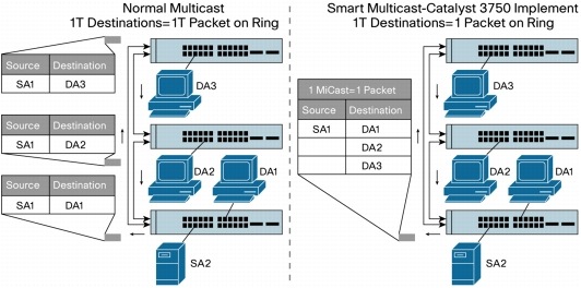
    The Cisco StackWise technology uses an extremely efficient mechanism for transmitting unicast and multicast traffic. Each data packet is put on the stack interconnect only once. This includes multicast packets. Each data packet has a 24-byte header with an activityJame list for the packet as well as a QoS designator. The activity list specifies the port destination or destinations and what should be done with the packet. In the case of multicast, the master switch identifies which of the ports should receive a copy of the packets and adds a destination index for each port. One copy of the packet is put on the stack interconnect. Each switch port that owns one of the destination index addresses then copies this packet. This creates a much more efficient mechanism for the stack to receive and manage multicast information (Figure 5).

    Figure 5. Comparison of Normal Multicast in Stackable Switches and Smart Multicast in Cisco Catalyst 3750 Series Switches Using Cisco StackWise Technology

    QoS Mechanisms

    QoS provides granular control where the user meets the network. This is particularly important for networks migrating to converged applications where differential treatment of information is essential. QoS is also necessary for the migration to Gigabit Ethernet speeds, where congestion must be avoided.

    QoS Applied at the Edge

    Cisco StackWise supports a complete and robust QoS model, as shown in Figure 6.

    Figure 6. QoS Model

    The Cisco Catalyst 3750-E, Catalyst 3750-X and Cisco Catalyst 3750 support 2 ingress queues and 4 egress queues. Thus the Cisco Catalyst 3750-E, Catalyst 3750-X and Cisco Catalyst 3750 switches. support the ability to not only limit the traffic destined for the front side ports, but they can also limit the amounts of and types of traffic destined for the stack ring interconnect. Both the ingress and egress queues can be configured for one queue to be serviced as a priority queue that gets completely drained before the other weighted queue(s) get serviced. Or, each queue set can be configured to have all weighted queues.

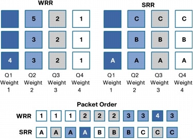
    StackWise employs Shaped Round Robin (SRR). SRR is a scheduling service for specifying the rate at which packets are dequeued. With SRR there are two modes, Shaped and Shared (default). Shaped mode is only available on the egress queues. Shaped egress queues reserve a set of port bandwidth and then send evenly spaced packets as per the reservation. Shared egress queues are also guaranteed a configured share of bandwidth, but do not reserve the bandwidth. That is, in Shared mode, if a higher priority queue is empty, instead of the servicer waiting for that reserved bandwidth to expire, the lower priority queue can take the unused bandwidth. Neither Shaped SRR nor Shared SRR is better than the other. Shared SRR is used when one wants to get the maximum efficiency out of a queuing system, because unused queue slots can be used by queues with excess traffic. This is not possible in a standard Weighted Round Robin (WRR). Shaped SRR is used when one wants to shape a queue or set a hard limit on how much bandwidth a queue can use. When one uses Shaped SRR one can shape queues within a ports overall shaped rate. In addition to queue shaping, the Cisco Catalyst 3750-E can rate limit a physical port. Thus one can shape queues within an overall rate-limited port value.

    As stated earlier, SRR differs from WRR. In the examples shown in figure 7, strict priority queuing is not configured and Q4 is given the highest weight, Q3 lower, Q2 lower, and Q1 the lowest. With WRR, queues are serviced based on the weight. Q1 is serviced for Weight 1 period of time, Q2 is served for Weight 2 period of time, and so forth. The servicing mechanism works by moving from queue to queue and services them for the weighted amount of time. With SRR weights are still followed; however, SRR services the Q1, moves to Q2, then Q3 and Q4 in a different way. It doesn't wait at and service each queue for a weighted amount of time before moving on to the next queue. Instead, SRR makes several rapid passes at the queues, in each pass, each queue may or may not be serviced. For each given pass, the more highly weighted queues are more likely to be serviced than the lower priority queues. Over a given time, the number of packets serviced from each queue is the same for SRR and WRR. However, the ordering is different. With SRR, traffic has a more evenly distributed ordering. With WRR one sees a bunch of packets from Q1 and then a bunch of packets from Q2, etc. With SRR one sees a weighted interleaving of packets. In the example in Figure 7, for WRR, all packets marked 1 are serviced, then 2, then 3, and so on till 5. In SRR, all A packets are serviced, then B, C, and D. SRR is an evolution of WRR that protects against overwhelming buffers with huge bursts of traffic by using a smoother round-robin mechanism.

    Figure 7. Queuing

    In addition to advanced queue servicing mechanisms, congestion avoidance mechanisms are supported. Weighted tail drop (WTD) can be applied on any or all of the ingress and egress queues. WTD is a congestion-avoidance mechanism for managing the queue lengths and providing drop precedences for different traffic classifications. Configurable thresholds determine when to drop certain types of packets. The thresholds can be based on CoS or DSCP values. As a queue fills up, lower priority packets are dropped first. For example, one can configure WTD to drop CoS 0 through 5 when the queue is 60% full. In addition, multiple thresholds and levels can be set on a per queue basis.

    Jumbo Frame Support

    The Cisco StackWise technology supports granular jumbo frames up to 9 KB on the 10/100/1000 copper ports for Layer 2 forwarding. Layer 3 forwarding of jumbo packets is not supported by the Cisco Catalyst 3750. However, the Cisco Catalyst 3750-E and Catalyst 3750-X. do support Layer 3 jumbo frame forwarding.

    Smart VLANs

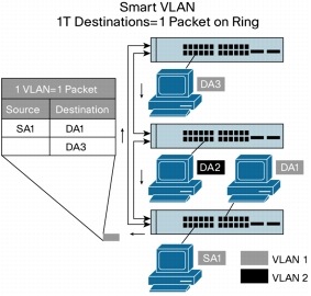
    VLAN operation is the same as multicast operation. If the master detects information that is destined for multiple VLANs, it creates one copy of the packet with many destination addresses. This enables the most effective use of the stack interconnect (Figure 8).

    Figure 8. Smart VLAN Operations

    Cross-Stack EtherChannel Connections

    Because all the ports in a stack behave as one logical unit, EtherChannel technology can operate across multiple physical devices in the stack. Cisco IOS Software can aggregate up to eight separate physical ports from any switches in the stack into one logical channel uplink. Up to 48 EtherChannel groups are supported on a stack.

    StackWise Plus

    StackWise Plus is an evolution of StackWise. StackWise Plus is only supported on the Cisco Catalyst 3750-E and Catalyst 3750-X switch families. The two main differences between StackWise Plus and StackWise are as follows:

    1. For unicast packets, StackWise Plus supports destination striping, unlike StackWise support of source stripping. Figure 9 shows a packet is being sent from Switch 1 to Switch 2. StackWise uses source stripping and StackWise Plus uses destination stripping. Source stripping means that when a packet is sent on the ring, it is passed to the destination, which copies the packet, and then lets it pass all the way around the ring. Once the packet has traveled all the way around the ring and returns to the source, it is stripped off of the ring. This means bandwidth is used up all the way around the ring, even if the packet is destined for a directly attached neighbor. Destination stripping means that when the packet reaches its destination, it is removed from the ring and continues no further. This leaves the rest of the ring bandwidth free to be used. Thus, the throughput performance of the stack is multiplied to a minimum value of 64 Gbps bidirectionally. This ability to free up bandwidth is sometimes referred to as spatial reuse. Note: even in StackWise Plus broadcast and multicast packets must use source stripping, because the packet may have multiple targets on the stack.

    Figure 9. Stripping

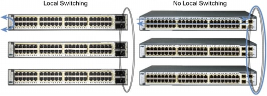
    2. StackWise Plus can locally switch. StackWise cannot. Furthermore, in StackWise, since there is no local switching and since there is source stripping, even locally destined packets must traverse the entire stack ring. (See Figure 10.)

    Figure 10. Switching

    3. StackWise Plus will support up to 2 line rate 10 Gigabit Ethernet ports per Cisco Catalyst 3750-E.

    Combining StackWise Plus and StackWise in a Single Stack

    Cisco Catalyst 3750-E and Catalyst 3750-X StackWise Plus and Cisco Catalyst 3750 StackWise switches can be combined in the same stack. When this happens, the Cisco Catalyst 3750-E, or Catalyst 3750-Xswitches negotiate from StackWise Plus mode down to StackWise mode. That is, they no longer perform destination stripping. However, the Cisco Catalyst 3750-E and the Catalyst 3750-X will retain its ability to perform local switching.

    Management

    Products using the Cisco StackWise and StackWise Plus technologies can be managed by the CLI or by network management packages. Cisco Cluster Management Suite (CMS) Software has been developed specifically for management of Cisco stackable switches. Special wizards for stack units in Cisco CMS Software allow the network manager to configure all the ports in a stack with the same profile. Predefined wizards for data, voice, video, multicast, security, and inter-VLAN routing functions allow the network manager to set all the port configurations at once.

    The Cisco StackWise and StackWise Plus technologies are also manageable by CiscoWorks.

    Summary

    Cisco StackWise and StackWise Plus technologies allow you to increase the resiliency and the versatility of your network edge to accommodate evolution for speed and converged applications. 
    Read more »
  • The Composition and Classification of Fiber Optic Cables

    To satisfy optical, mechanical and environmental performances and specifications, fiber optic cable was born. The fiber optic cable uses one or more fibers that placed in the sheath as the transmission medium. Accompanied by the continuous advancement of network technology, fiber optic cable constantly participates in the construction of telecommunications networks, the construction of the national information highway, Fiber To The Home (FTTH) and other occasions for large-scale use. Although fiber optic cable is still more expensive than other types of cable, it's favored for today's high-speed data communications because it eliminates the problems of twisted-pair cable and so fiber optic cable is still a good choice for people. But how to really get a good performance, state-of-the-art products, we need to understand some basics to identify the types of fiber optic cables.

    Composition

    Fiber optic cable consists of the core, the cladding and the coating. The core is a cylindrical rod of dielectric material. Dielectric material conducts no electricity. Light propagates mainly along the core of the fiber. The core is generally made of glass. The core is described as having a radius of (a) and an index of refraction n1. The core is surrounded by a layer of material called the cladding. Even though light will propagate along the fiber core without the layer of cladding material, the cladding does perform some necessary functions. (The basic structure of an optical fiber is shown in the following figure.)


    Structure: Core: This central section, made of silica, is the light transmitting region of the fiber.Cladding: It is the first layer around the core. It is also made of silica, but not with the same composition as the core. This creates an optical wave guide which confines the light in the core by total reflection at the core-cladding interface.Coating: It is the first non-optical layer around the cladding. The coating typically consists of one or more layers of a polymer that protect the silica structure against physical or environmental damage.Strengthening Fibers: These components help protect the core against crushing forces and excessive tension during installation. The materials can range from Kevlar to wire strands to gel-filled sleeves.Cable Jacket: This is the outer layer of any cable. Most fiber optic cables have an orange jacket, although some may be black or yellow. The jacket material is application specific. The cable jacket material determines the mechanical robustness, aging due to UV radiation, oil resistance, etc.


    Jacket Material: PolyEthylene (PE): PE (black color) is the standard jacket material for outdoor fiber optic cables. PE has excellent moisture- and weather-resistance properties. It has very stable dielectric properties over a wide temperature range. It is also abrasion-resistant.PolyVinyl Chloride (PVC): PVC is the most common material for indoor cables, however it can also be used for outdoor cables. It is flexible and fire-retardant. PVC is more expensive than PE.PolyVinyl DiFluoride (PVDF): PVDF is used for plenum cables because it has better fire-retardant properties than PE and produces little smoke.Low Smoke Zero Halogen (LSZH) Plastics: LSZH plastics are used for a special kind of cable called LSZH cables. They produce little smoke and no toxic halogen compounds. But they are the most expensive jacket material. 


    Fiber Size

    The size of the optical fiber is commonly referred to by the outer diameter of its core, cladding and coating. Example: 50/125/250 indicates a fiber with a core of 50 microns, cladding of 125 microns, and a coating of 250 microns. The coating is always removed when joining or connecting fibers. A micron (µm) is equal to one-millionth of a meter. 25 microns are equal to 0.0025 cm. (A sheet of paper is approximately 25 microns thick).


    Classification

    Besides the basics, Fiber optic cables can be classified by other ways.

    Transmission Mode:
    • Multi-Mode Fiber (MMF) Cable: Center glass core is coarse (50 or 62.5 µm). It can transmit a variety of patterns of light. However, because its dispersion is large, which limits the frequency of the transmitted digital signal, and with increasing distance, the situation will be more serious. For example, 600Mb/km of 2km fibers provide the bandwidth of only 300 Mbps. Therefore, MMF cable's transmission distance is relatively short, generally only a few kilometers. General MMF patch cables are in orange, also some are gray, joints and protection are beige or black. 
    • Single-Mode Fiber SMF Cable: Center glass core is relatively fine (core diameter is generally 9 or 10 µm), only one mode of light transmission. Therefore, the dispersion is very small, suitable for remote communication, but it plays a major role in the chromatic dispersion, so that SMF cable has a higher stability requirement to the spectral width of the light source, just as narrower spectrum width, better stability. General SMF patch cables are in yellow, with joints and cases in blue.


    Transmission Way:
    • Simplex Cable: Single strand of fiber surrounded by a 900µm buffer then a layer of Kevlar and finally the outer jacket. Available in 2 mm or 3 mm and plenum or riser jacket. Plenum is stronger and made to share in fire versus riser is made to melt in fire. Riser cable is more flexible.
    • Duplex Cable: Two single strands of fiber optic cable attached at the center. Surrounded by a 900µm buffer then a layer of Kevlar and finally the outer jacket. In data communications, the simultaneous operation of a circuit in both directions is known as full duplex; if only one transmitter can send at a time, the system is called half duplex.


    Cable Core Structure:
    • Central Tube Cable: Fiber, optical fiber bundles or fiber optic cable with no stranding directly into the center position.
    • Stranded Tube Cable: A few dozens or more root fiber or fiber tape unit helically stranded around the central strength member (S twist or SZ twisted) into one or more layers of fiber optic cable.
    • Skeleton After Tube Cable: Fiber or fiber after spiral twisted placed into the plastic skeleton cable slot.


    Fiber Road Laying:
    • Aerial Cable: Aerial cables are for outside installation on poles. They can be lashed to a messenger or another cable (common in CATV) or have metal or aramid strength members to make them self supporting. The cable shown has a steel messenger for support. It must be grounded properly. A widely used aerial cable is optical power ground wire which is a high voltage distribution cable with fiber in the center. The fiber is not affected by the electrical fields and the utility installing it gets fibers for grid management and communications. This cable is usually installed on the top of high voltage towers but brought to ground level for splicing or termination. 
    • Direct-Buried Cables:
      • Armored Cable: Armored cable is used in direct-buried outside plant applications where a rugged cable is needed and/or rodent resistance. Armored cable withstands crush loads well, needed for direct burial applications. Cable installed by direct burial in areas where rodents are a problem usually have metal armoring between two jackets to prevent rodent penetration. Another application for armored cable is in data centers, where cables are installed underfloor and one worries about the fiber cable being crushed. Armored cable is conductive, so it must be grounded properly. 
      • Breakout Cable: Breakout cable is a favorite where rugged cables are desirable or direct termination without junction boxes, patch panels or other hardware is needed. It is made of several simplex cables bundled together inside a common jacket. It has a strong, rugged design, but is larger and more expensive than the distribution cables. It is suitable for conduit runs, riser and plenum applications. It's perfect for industrial applications where ruggedness is needed. Because each fiber is individually reinforced, this design allows for quick termination to connectors and does not require patch panels or boxes. Breakout cable can be more economic where fiber count is not too large and distances are not too long, because it requires so much less labor to terminate.
    • Submarine Cable: Submarine cable is the cable wrapped with insulating materials, laying at the bottom of the sea, to set up a telecom transmission between countries.


    Cable State. Based on 900µm tight buffered fiber and 250µm coated fiber there are two basic types of fiber optic cable constructions:
    • Tight Buffered Cable: Multiple color coded 900µm tight buffered fibers can be packed tightly together in a compact cable structure, an approach widely used indoors, these cables are called tight buffered cables. Tight buffered cables are used to connect outside plant cables to terminal equipment, and also for linking various devices in a premises network. Multi-fiber tight buffered cables often are used for intra-building, risers, general building and plenum applications. Tight buffered cables are mostly built for indoor applications, although some tight buffered cables have been built for outdoor applications too.
    • Loose Tube Cable: On the other hand multiple (up to 12) 250µm coated fibers (bare fibers) can be put inside a color coded, flexible plastic tube, which usually is filled with a gel compound that prevents moisture from seeping through the hollow tube. Buffer tubes are stranded around a dielectric or steel central member. Aramid yarn are used as primary strength member. Then an outer polyethylene jacket is extruded over the core. These cables are called loose tube cables. Loose tube structure isolates the fibers from the cable structure. This is a big advantage in handling thermal and other stresses encountered outdoors, which is why most loose tube fiber optic cables are built for outdoor applications. Loose-tube cables typically are used for outside-plant installation in aerial, duct and direct-buried applications. 


    Environment & Situation:
    • Indoor Cable: Such as distribution cables. Distribution cable is the most popular indoor cable, as it is small in size and light in weight. They contain several tight-buffered fibers bundled under the same jacket with Kevlar strength members and sometimes fiberglass rod reinforcement to stiffen the cable and prevent kinking. These cables are small in size, and used for short, dry conduit runs, riser and plenum applications. The fibers are double buffered and can be directly terminated, but because their fibers are not individually reinforced, these cables need to be broken out with a "breakout box" or terminated inside a patch panel or junction box to protect individual fibers.
    • Outdoor Cable: Outdoor fiber cable delivers outstanding audio, video, telephony and data signal performance for educational, corporate and government campus applications. With a low bending radius and lightweight feature, this cable is suitable for both indoor and outdoor installations. These are available in a variety of configurations and jacket types to cover riser and plenum requirements for indoor cables and the ability to be run in duct, direct buried, or aerial/lashed in the outside plant.

    To purchase your fiber cables, please click link below:

    Fiber Patch Cables


    Read more »
  • Optics and Cables Selection for Storage Area Network (SAN)

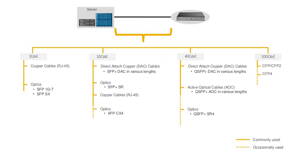
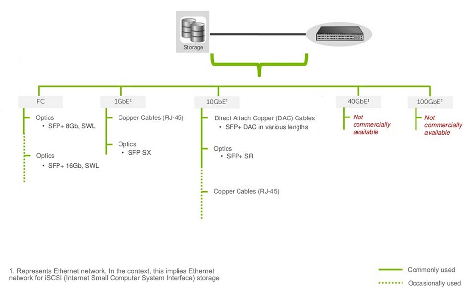
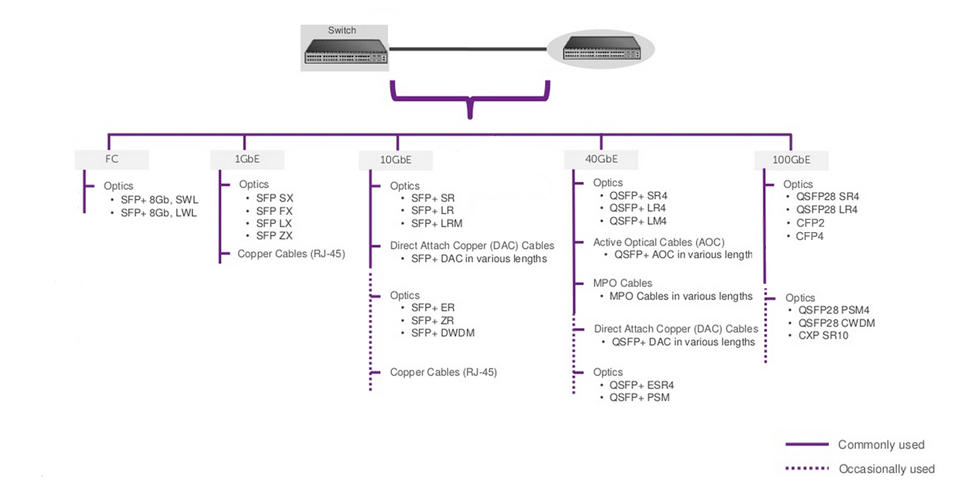
    Optics and cables are the most important infrastructures of network connectivity. In a storage area network (SAN), switches are used between servers and storage devices. This means that you should make connection with optics and cables between the server and switch, storage and switch as well as the switch and switch. Of course, according to different application environments, you should choose different optics and cables in order to get the best performance. Furthermore, you may need to consider the future expansion of your network. Thus, an economical and effective solution of optics and cables are very necessary.

    Key Factors Influencing Your Decision

    Firstly, there are some key factors which will influence your decision. Thus, you must make sure that what your network really requires. As we mentioned above, an SAN has server, storage device and switches. So, what should we consider in every section of the network?

    1. Server
    Bandwidth: Depending on the application load requirements, customers typically decide whether they want 1GbE, 10GbE, or 40GbE. In some cases, the decision may also be dictated by the type of traffic, e.g. DCB (Data center bridging) requires 10GbE or higher.Cost: Servers claim the highest share of devices deployed in any data center. Choosing a lower cost connectivity option results in a much lower initial deployment cost.Power: In any high density server deployment, a connectivity option which consumes lower power results in much lower OpEx.Distance: Servers are typically connected to a switch over a very short distance, i.e. typically within the same rack or, in some cases, within the same row.Cabling Flexibility: Some customer prefer to make their own copper cables due to variable distance requirement. This requirement limits the choice of connectivity to copper cables only.


    2. Storage
    Reliability: Typical storage traffic is very sensitive to loss. Even a minor loss of traffic may result in major impact on application performance.Qualification: Storage vendor qualification or recommendation plays an important role in this decision due to reasons such as customer support, peace of mind, etc.Latency: Any time spent in transition is time taken away from data processing. Reducing transition time results in much faster application performance. The result may have a direct impact on customers' bottom line, e.g. faster processing of online orders.


    3. Switch
    Bandwidth: On server facing ports, servers typically dictate the per port bandwidth requirement. However, per port bandwidth requirement for the network facing (switch-to-switch) ports denpends on multiple factors including amount of traffic generated by the servers, oversubscription ratios, fiber limitations, ect.Distance: An inter-switch or switch to router connection could range from a few inches to tens of kilometers. Generally, the price of optics increases as the distance increases.Latency: The network topology and application traffic profile (East-west, HPC (High Performance Computing), computer cluster, etc.) and influence the minimun latency that can be tolerated in the network.


    • Server to Switch Connectivity Solution

    • Storage to Switch Connectivity Solution


    • Switch to Switch Connectivity Solution


     COMPUFOX Solutions

    COMPUFOX  offers a comprehensive solution of optics and cables which supports your network from 1GbE to 100GbE. We have a great selection of 1000BASE-T/SX/LX SFP, BiDi SFP, 10GBASE-SR/LR SFP+, DWDM SFP+, whole series 40G QSFP+ optics and cables, as well as the 100G CFP2 and CFP4, etc. which help you solve the cost issue in fiber project. Especially the 40G QSFP+ optics, with the passive optic design, they can be compatible with all the equipment of all major brands. In addition, most of them are ready stock. See Links below:

    Read more »
  • Polarization-Maintaining Fiber Tutorial

    Introduction to Polarization

    As light passes through a point in space, the direction and amplitude of the vibrating electric field traces out a path in time. A polarized lightwave signal is represented by electric and magnetic field vectors that lie at right angles to one another in a transverse plane (a plane perpendicular to the direction of travel). Polarization is defined in terms of the pattern traced out in the transverse plane by the electric field vector as a function of time.

    Polarization can be classified as linear, elliptical or circular, in them the linear polarization is the simplest. Whichever polarization can be a problem in the fiber optic transmission.

    FiberStore Polarization Coordinate System

    More and more telecommunication and fiber optic measuring systems refer to devices that analyse the interference of two optical waves. The information given by the interferences cannot be used unless the combined amplitude is stable in time, which means, that the waves are in the same state of polarization. In those cases it is necessary to use fibers that transmit a stable state of polarization. And polarization-maintaining fiber was developed to this problem. (The polarization-maintaining fiber will be called PM fiber for short in the following contents.)


    What Is PM Fiber?

    The polarization of light propagating in the fiber gradually changes in an uncontrolled (and wavelength-dependent) way, which also depends on any bending of the fiber and on its temperature. Specialised fibers are required to achieve optical performances, which are affected by the polarization of the light travelling through the fiber. Many systems such as fiber interferometers and sensors, fiber laser and electro-optic modulators, also suffer from Polarization-Dependent Loss (PDL) that can affect system performance. This problem can be fixed by using a specialty fiber so called PM Fiber.


    Principle of PM Fiber

    Provided that the polarization of light launched into the fiber is aligned with one of the birefringent axes, this polarization state will be preserved even if the fiber is bent. The physical principle behind this can be understood in terms of coherent mode coupling. The propagation constants of the two polarization modes are different due to the strong birefringence, so that the relative phase of such copropagating modes rapidly drifts away. Therefore, any disturbance along the fiber can effectively couple both modes only if it has a significant spatial Fourier component with a wavenumber which matches the difference of the propagation constants of the two polarization modes. If this difference is large enough, the usual disturbances in the fiber are too slowly varying to do effective mode coupling. Therefore, the principle of PM fiber is to make the difference large enough.

    In the most common optical fiber telecommunications applications, PM fiber is used to guide light in a linearly polarised state from one place to another. To achieve this result, several conditions must be met. Input light must be highly polarised to avoid launching both slow and fast axis modes, a condition in which the output polarization state is unpredictable.

    The electric field of the input light must be accurately aligned with a principal axis (the slow axis by industry convention) of the fiber for the same reason. If the PM fiber path cable consists of segments of fiber joined by fiber optic connectors or splices, rotational alignment of the mating fibers is critical. In addition, connectors must have been installed on the PM fibers in such a way that internal stresses do not cause the electric field to be projected onto the unintended axis of the fiber.


    Types of PM Fibers

    Circular PM Fibers

    It is possible to introduce circular-birefringence in a fiber so that the two orthogonally polarized modes of the fiber—the so called Circular PM fiber—are clockwise and counter-clockwise circularly polarized. The most common way to achieve circular-birefringence in a round (axially symmetrical) fiber is to twist it to produce a difference between the propagation constants of the clockwise and counterclockwise circularly polarized fundamental modes. Thus, these two circular polarization modes are decoupled. Also, it is possible to conceive externally applied stress whose direction varies azimuthally along the fiber length causing circular-birefringence in the fiber. If a fiber is twisted, a torsional stress is introduced and leads to optical-activity in proportion to the twist.

    Circular-birefringence can also be obtained by making the core of a fiber follows a helical path inside the cladding. This makes the propagating light, constrained to move along a helical path, experience an optical rotation. The birefringence achieved is only due to geometrical effects. Such fibers can operate as a single mode, and suffer high losses at high order modes.

    Circular PM fiber with Helical-core finds applications in sensing electric current through Faraday effect. The fibers have been fabricated from composite rod and tube preforms, where the helix is formed by spinning the preform during the fiber drawing process.


    Linear PM Fibers

    There are manily two types of linear PM fibers which are single-polarization type and birefringent fiber type. The single-polarization type is characterized by a large transmission loss difference between the two polarizations of the fundamental mode. And the birefringent fiber type is such that the propagation constants between the two polarizations of the fundamental mode are significantly different. Linear polarization may be maintained using various fiber designs which are reviewed next.

    Linear PM Fibers With Side Pits and Side Tunnels

    Side-pit fibers incorporate two pits of refractive index less than the cladding index, on each side of the central core. This type of fiber has a W-type index profile along the x-axis and a step-index profile along the y-axis. A side-tunnel fiber is a special case of side-pit structure. In these linear PM fibers, a geometrical anisotropy is introduced in the core to obtain a birefringent fibers.


    Linear PM Fibers With Stress Applied Parts

    An effective method of introducing high birefringence in optical fibers is through introducing an asymmetric stress with two-fold geometrical symmetry in the core of the fiber. The stress changes the refractive index of the core due to photoelastic effect, seen by the modes polarized along the principal axes of the fiber, and results in birefringence. The required stress is obtained by introducing two identical and isolated Stress Applied Parts (SAPs), positioned in the cladding region on opposite sides of the core. Therefore, no spurious mode is propagated through the SAPs, as long as the refractive index of the SAPs is less than or equal to that of the cladding.

    The most common shapes used for the SAPs are: bow-tie shape and circular shape. These fibers are respectively referred to as Bow-tie Fiber and PANDA Fiber. The cross sections of these two types of fibers are shown in the figure below. The modal birefringence introduced by these fibers represents both geometrical and stress-induced birefringences. In the case of a circular-core fiber, the geometrical birefringence is negligibly small. It has been shown that placing the SAPs close to the core improves the birefringence of these fibers, but they must be placed sufficiently close to the core so that the fiber loss is not increased especially that SAPs are doped with materials other than silica. The PANDA fiber has been improved further to achieve high modal birefringence, very low-loss and low cross-talk.

    PANDA Fiber and Bow-tie Fiber

    PANDA Fiber (left) and Bow-tie Fiber (right). The built-in stress elements made from a different type of glass are shown with a darker gray tone.

    Tips: At present the most popular PM fiber in the industry is the circular PANDA fiber. One advantage of PANDA fiber over most other PM fibers is that the fiber core size and numerical aperture is compatible with regular single mode fiber. This ensures minimum losses in devices using both types of fibers.


    Linear PM Fibers With Elliptical Structures

    The first proposal on practical low-loss single-polarization fiber was experimentally studied for three fiber structures: elliptical core, elliptical clad, and elliptical jacket fibers. Early research on elliptical-core fibers dealt with the computation of the polarization birefringence. In the first stage, propagation characteristics of rectangular dielectric waveguides were used to estimate birefringence of elliptical-core fibers. In the first experiment with PM fiber, a fiber having a dumbbell-shaped core was fabricated. The beat length can be reduced by increasing the core-cladding refractive index difference. However, the index difference cannot be increased too much due to practical limitations. Increasing the index difference increases the transmission loss, and splicing would become difficult because the core radius must be reduced. Typical values of birefringence for the elliptical core fiber are higher than elliptical clad fiber. However, losses were higher in the elliptical core than losses in the elliptical clad fibers.


    Linear PM Fibers With Refractive Index Modulation

    One way to increase the bandwidth of single-polarization fiber, which separates the cutoff wavelength of the two orthogonal fundamental modes, is by selecting a refractive-index profile which allows only one polarization state to be in cutoff. High birefringence was achieved by introducing an azimuthal modulation of the refractive index of the inner cladding in a three-layer elliptical fiber. A perturbation approach was employed to analyze the three-layer elliptical fiber, assuming a rectangular-core waveguide as the reference structure. Examination of birefringence in three-layer elliptical fibers demonstrated that a proper azimuthal modulation of the inner cladding index can increase the birefringence and extend the wavelength range for single-polarization operation.

    A refractive index profile is called Butterfly profile. It is an asymmetric W profile, consisting of a uniform core, surrounded by a cladding in which the profile has a maximum value of ncl and varies both radially and azimuthally, with maximum depression along the x-axis. This profile has two attributes to realize a single-mode single-polarization operation. First, the profile is not symmetric, which makes the propagation constants of the two orthogonal fundamental modes dissimilar, and secondly, the depression within the cladding ensures that each mode has a cutoff wavelength. The butterfly fiber is weakly guiding, thus modal fields and propagation constants can be determined from solutions of the scalar wave equation. The solutions involve trigonometric and Mathieu functions describing the transverse coordinates dependence in the core and cladding of the fiber. These functions are not orthogonal to one another which requires an infinite set of each to describe the modal fields in the different regions and satisfy the boundary conditions. The geometrical birefringence plots generated vs. the normalized frequency V showed that increasing the asymmetry through the depth of the refractive index depression along the x-axis increases the maximum value of the birefringence and the value of V at which this occurs. The peak value of birefringence is a characteristic of noncircular fibers. The modal birefringence can be increased by introducing anisotropy in the fiber which can be described by attributing different refractive-index profiles to the two polarizations of a mode. The geometric birefringence is smaller than the anisptropic birefringence. However, the depression in the cladding of the butterfly profile gives the two polarizations of fundamental mode cutoff wavelengths, which are separated by a wavelength window in which single-polarization single-mode operation is possible.


    Applications of PM Fibers

    PM fibers are applied in devices where the polarization state cannot be allowed to drift, e.g. as a result of temperature changes. Examples are fiber interferometers and certain fiber lasers. A disadvantage of using such fibers is that usually an exact alignment of the polarization direction is required, which makes production more cumbersome. Also, propagation losses are higher than for standard fiber, and not all kinds of fibers are easily obtained in polarization-preserving form.

    PM fibers are used in special applications, such as in fiber optic sensing, interferometry and quantum key distribution. They are also commonly used in telecommunications for the connection between a source laser and a modulator, since the modulator requires polarized light as input. They are rarely used for long-distance transmission, because PM fiber is expensive and has higher attenuation than single mode fiber.


    Requirments for Using PM Fibers

    Termination: When PM fibers are terminated with fiber connectors, it is very important that the stress rods line up with the connector, usually in line with the connector key.

    Splicing: PM fiber also requires a great deal of care when it is spliced. Not only the X, Y and Z alignment have to be perfect when the fiber is melted together, the rotational alignment must also be perfect, so that the stress rods align exactly.

    Another requirement is that the launch conditions at the optical fiber end face must be consistent with the direction of the transverse major axis of the fiber cross section.

    Read more »
RSS